
Oval Gear Flow Meters: How They Measure Diesel and Other Viscous Fluids Accurately

Quick Answer
An oval gear flow meter measures liquid volume by counting how many fixed chambers pass through it, which makes it accurate on diesel, oils and other viscous fluids. This guide explains how it works, where it fits, and how to install it.
Diesel is one of the largest line items on a factory's utility bill, and it is often the least measured. A tank dipstick gives a reading good to a centimeter or two, a delivery ticket gives a figure from the tanker, and the difference between the two is explained by temperature and optimism. A generator set burns a few hundred liters an hour, a boiler burns more, and a small loss that nobody can see, from leakage, theft, a faulty injector or a drifting setpoint, adds up to a tank of fuel by the end of the month. A meter on the supply line shows where every liter went.
An oval gear flow meter is a positive displacement flow meter that measures liquid by volume. Two oval gears mesh and rotate inside a precisely machined chamber, and each turn passes a fixed quantity of fluid, so counting the turns gives the volume. It handles viscous liquids better than most other technologies, it needs no electrical power for a mechanical version, and it suits diesel, lubricating oil, hydraulic oil, resins, inks and syrups. This guide explains the working principle, how viscosity affects accuracy, where a diesel flow meter and other fuel flow meters are used, how to install and calibrate one, and what goes wrong, with an example drawn from diesel monitoring at an industrial site.
Why Diesel and Oils Need a Flow Meter That Counts Volume
Many flow technologies struggle with fuels and oils. An electromagnetic meter needs a conductive liquid, and diesel is not conductive. A turbine meter loses accuracy as viscosity rises and wears faster in a fluid with little lubricity. An ultrasonic meter works, but its accuracy on a small pipe is lower than a positive displacement type. A Coriolis meter is excellent and costs several times more. For many fuel and oil duties, the right answer is a meter that physically counts volume.
A positive displacement flow meter works like a bucket and a stopwatch, built into a pipe. The meter has a measuring chamber of known volume, the fluid fills it, the mechanism empties it, and a counter records how many times that happened. It does not care about the velocity profile, it needs no straight pipe run, and its accuracy holds across a wide range of flow rates when the fluid is clean. That simplicity is the reason oval gear meters have been used on fuel lines for decades.
How an Oval Gear Flow Meter Works
Inside the housing, two oval-shaped gears sit side by side with their teeth meshed. They are mounted on shafts and rotate at right angles to each other. The pressure difference between the inlet and the outlet, created by the fluid being pushed through, drives the rotation. The fluid does not need a motor or a pump in the meter.
Between each gear and the wall of the chamber is a crescent-shaped space that traps a fixed quantity of liquid. As one gear turns, it carries that crescent from the inlet side to the outlet side and releases it, while the other gear is doing the same on the opposite side. In one full turn of the gear pair, four crescent volumes are transferred. Because the dimensions are fixed by machining, the volume per turn is fixed, and the fluid's own flow turns the gears at a rate proportional to the flow.
A magnet embedded in one gear passes a sensor, such as a reed switch or a Hall-effect device, and each pass generates a pulse. Each pulse corresponds to a known volume. The pulses go to a local display, a totalizer, a flow computer, a PLC or a batch controller. A mechanical register, driven through a magnetic coupling, shows the total without electricity. The meter measures volumetric flow, and because gears turn in only one direction of flow, most oval gear meters are unidirectional.
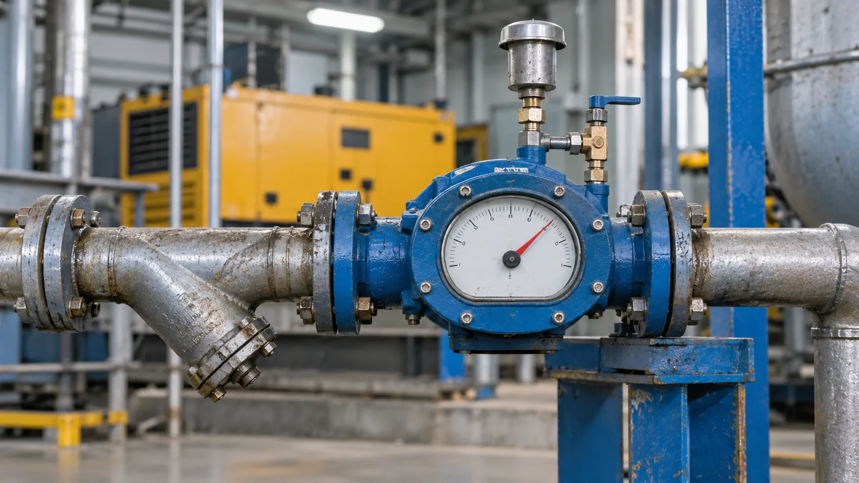
A typical industrial unit has a cast housing with flanged connections, a digital or mechanical totalizer on top, and a nameplate showing the flow range, the viscosity range, the pressure rating and the accuracy class, which is 0.2 percent on some models. The nameplate is the first thing to read on any oval gear meter, because the range and the viscosity limits are specific to the model.
A positive displacement meter does not estimate volume from velocity. It counts buckets, so what it needs from the installation is a full pipe and clean fluid.
Accuracy, Viscosity and Why Diesel Sits at the Edge
Typical published accuracy for an oval gear flow meter is ±0.5 percent of reading with a single-point calibration, improving to about ±0.2 percent with a multi-point calibration. The figures hold in the viscosity range the meter was designed for and on clean fluid.
Viscosity has two opposing effects. A thicker fluid fills the clearances between the gears and the housing, which reduces slip, the small leakage of fluid past the gears without being counted, so accuracy improves with viscosity. The same thick fluid raises the pressure drop needed to turn the gears, so the meter's usable flow range falls, and at very high viscosity the meter may stall. Manufacturers state a minimum and a maximum viscosity, and some models run to 1000 cP or more.
Diesel sits near the low end. A typical diesel fuel has a viscosity of about 2 to 4.5 cSt at 40 °C, which is roughly 1.7 to 3.7 cP at its density. Some sources warn that below about 3 cP, or with fluids of low lubricity, the usable flow range and accuracy of an oval gear meter can suffer, because slip increases and the gears are less protected by a lubricating film. Low-sulphur diesel has less lubricity than older grades. That does not rule out oval gear meters on diesel, since they are widely used on it, but it means the meter must be specified for low-viscosity fuel, with tight clearances, and calibrated on diesel. A meter selected for heavy oil and then used on diesel can under-read by a visible margin.
Temperature changes viscosity and volume together. Diesel thickens as it cools, which improves accuracy and raises pressure drop, and it expands about 0.08 percent for each degree Celsius, so a 25 °C swing between a cool night and a hot afternoon changes the volume of a given mass of fuel by about 2 percent. A volume meter reports the volume it sees, and the plant has to decide whether to correct it to a reference temperature, 15 °C being the usual reference for fuels. Our post on types of industrial flowmeters covers the other options for that decision.
Positive Displacement Flow Meter Types: Where Oval Gear Fits
Oval gear is one of several designs in the positive displacement family. All count volume in fixed chambers, and they differ in mechanism, in what they tolerate and in what they cost.
| Type | Mechanism | Suited to | Limits |
|---|---|---|---|
| Oval gear | Two meshed oval gears in a chamber | Fuels, oils, resins, syrups, viscous liquids | Needs clean fluid, unidirectional, gear wear |
| Nutating disc | A disc wobbles in a chamber | Water, domestic and commercial water meters | Low viscosity range |
| Rotary vane | Vanes slide in a rotor | Fuel dispensing, low-viscosity fuels | Wear, sensitive to dirt |
| Helical rotor | Two screw-shaped rotors | High-viscosity fluids, crude oil, bitumen | Cost, size |
| Piston and rotating piston | Pistons displace volume | Small flows, precise batching | Pulsation, wear |
Several uses of the term cause confusion. A positive displacement flow meter can also refer to water meters, which are usually nutating-disc designs, and to household gas meters, which use diaphragms. When someone says oval gear, they mean the type in the first row, which is the industrial workhorse for fuel and oil.
Diesel Flow Meter and Fuel Flow Meters in Practice
A diesel fuel flow meter on an industrial site does one of four jobs. It measures fuel to a generator set, to find the consumption in liters per hour and the specific consumption in liters per kilowatt-hour, which exposes engine problems and poor loading. It measures fuel to a boiler or furnace burner, to track efficiency and to bill internal cost centers. It measures fuel unloaded from a tanker into a storage tank, to check the delivery against the ticket. And it measures fuel dispensed to vehicles or mobile equipment, to control stock and detect loss.
Engines add a wrinkle. A diesel engine pumps more fuel than it burns and returns the surplus to the tank, so true consumption is the supply flow minus the return flow. Plants measure both with two meters, or with one meter and a differential arrangement, and subtract. A single meter on the supply line alone overstates consumption. This approach is common on marine and genset installations, and a marine diesel fuel flow meter pair is the usual answer for the same reason on ships.
Mining, construction and transport fleets use fuel flow meters on fuel trucks and dispensers to control a large and attractive stock. Commercial dispensing for sale needs a meter approved for legal metrology, and the requirement comes from the national rules; for monitoring inside a plant, a calibrated meter without legal approval is adequate.
Other liquids follow the same logic. An oil flow meter on a lubrication system, a hydraulic power pack or a transformer filling line counts oil volume reliably. Paint, ink and resin lines use oval gear meters because the fluids are viscous and a meter without moving parts in the flow path would be inaccurate. In every case, the fluid must be free of hard particles.
Installation: Strainer, Air Eliminator and Flushing
Most oval gear failures come from installation, not from the meter. Debris is the first threat. The gears run with very small clearances, so a weld bead, a flake of rust or a piece of tank sludge jams them or scores the chamber. A strainer ahead of the meter, commonly a Y-type or basket strainer around 80 microns, is standard. It needs regular cleaning, because a blocked strainer starves the meter and distorts the readings. New pipework must be flushed before the meter goes in, and many installers fit a spool piece in place of the meter until the line is clean.
Air is the second. A positive displacement meter counts any gas that passes through it as liquid, so air in the line makes it over-register. Air gets in at the tanker connection, at a suction line leak or when a tank runs low. An air eliminator or a vent upstream, and a back-pressure valve downstream to keep the line full, remove the problem. A meter in a gravity-fed line that runs partly empty will not read correctly.
Flow control comes third. Fast valve closure creates pressure shock that can damage the gears, so downstream valves should close slowly, and a pump discharge should not slam into the meter. Over-speed does damage too. Keep the maximum flow below the meter's rating, and size the meter for the normal flow in the upper half of its range. Follow the manufacturer's orientation marks, since some models are designed for a specific shaft direction. Provide a bypass line and isolating valves, so the meter can be serviced without stopping the plant.
A pulse output goes to a counter or PLC through shielded cable. In a fuel area that is classified as hazardous, the pulse transmitter and the cable entries need certified protection, and the guide to Ex d versus Ex db marking explains what to read on the nameplate.
Calibration, Meter Factors and Temperature Correction
A pulse output from an oval gear meter comes with a K-factor, the number of pulses per liter. The manufacturer sets it from a factory calibration. In service, the real factor depends on the fluid and conditions, so a meter on diesel should be calibrated or proven on diesel at its operating temperature and flow.
The reference can be a master meter of higher accuracy, a calibrated volumetric prover or a weighed batch converted by density. The test compares the meter's total with the reference over a known volume, at several flow rates across the range. If the error is constant and small, a single meter factor corrects it. If the error changes with flow, as it does when slip is significant at low flow, a multi-point correction in the flow computer fixes it. Record the as-found result and the as-left result, and repeat the test at an interval that matches the duty, commonly yearly.
Temperature correction needs a decision. For fuel stock accounting, the usual practice is to convert the metered volume to the volume at 15 °C using the fuel's expansion coefficient or standard tables, and report that. A simple approach is to fit a temperature transmitter beside the meter and let the flow computer apply the correction. For monitoring consumption trends, uncorrected volume is acceptable provided the same method is used throughout, and the 2 percent seasonal swing is understood.
Failure Modes and Troubleshooting
Symptoms point to causes. Under-reading, where the meter shows less than the delivered volume, usually means wear that has opened the clearances, a viscosity lower than the meter was designed for, or an excessive pressure drop that is making the gears slip. Over-reading usually means air in the line. A meter that stops, or jerks, usually has debris in the gears, a blocked strainer or a fluid that has thickened in the cold. A meter that reads correctly at high flow and wrongly at low flow has slip that a multi-point calibration can correct. A pulse signal that is noisy or drops out points to cabling, a failing reed switch or electrical interference.
The full set of flowmeter failure patterns is in our guide to flowmeter troubleshooting, and the principles carry over. A routine of cleaning the strainer, checking the pulse count against a known delivery, and recording the differential pressure across the meter finds most problems before they become failures.
Real-World Scenario: Diesel Monitoring for an Industrial Site
TCC supplied oval gear flow meters to Unilever Pakistan for monitoring diesel flow. The figures below illustrate the reasoning and are not the plant's data.
Take a site with a 1 MW diesel generator set that runs about eight hours a day at 75 percent load. At roughly 0.27 liters per kilowatt-hour, the engine burns about 200 liters an hour, or 1600 liters a day. A dipstick on a 20,000 liter tank, read to about 1 percent of tank height, resolves several hundred liters at best, so a daily consumption figure from dips is only an estimate. An oval gear meter at ±0.5 percent measures the 1600 liters to within about 8 liters.
The installation follows the practice above. A strainer sits ahead of the meter, a vent removes air at the high point, and a second meter on the return line gives the net consumption. A pulse output goes to the plant's monitoring system. The control room now sees liters per hour, liters per kilowatt-hour and the daily total, and the plant can compare the figures with the generator's load. A rise in specific consumption flags an engine problem, such as a worn injector, long before it becomes a breakdown. A gap between the meter total and the stock reduction in the tank flags a leak or a loss.
The meter also settles arguments. When the tanker delivery is metered into the tank, the totalizer gives an independent volume at a known temperature, and the plant can compare it with the delivery ticket. A tidy record of the first month sets the baseline against which the following months are measured.
Choosing an Oval Gear Flow Meter
A short specification list settles most selections. Name the fluid, its viscosity range at the lowest and highest operating temperatures, and its cleanliness. State the minimum, normal and maximum flow. Define the pressure and temperature, and the line size and connection. Choose the materials, aluminum or cast iron for diesel and oil, stainless steel for solvents and food. Choose the output: a mechanical register, a pulse output, a 4–20 mA transmitter, or a batch controller. State the hazardous area class and the accuracy needed, and plan the strainer, air eliminator and bypass at the same time.
TCC's instrumentation and control team specifies, supplies and commissions fuel and oil flow meters, including strainers, air eliminators and calibration records. Where the meter feeds a generator or boiler, the generator overhauling and power generation service ties the fuel data to the engine's maintenance, and for plants that want the consumption in their control system, our industrial automation team brings the pulse output into the PLC. When the fluid, the accuracy or the budget points to another technology, the articles on Coriolis flowmeters and on clamp-on ultrasonic flow meters cover the main alternatives.
Frequently Asked Questions
How does an oval gear flow meter work?
Two oval gears mesh inside a measuring chamber and rotate as fluid pushes through. Each turn transfers a fixed volume of liquid in crescent-shaped spaces between the gears and the housing. A sensor counts the turns, usually through a magnet and a reed switch or Hall sensor, and the count converts directly to volume.
Can an oval gear flow meter measure diesel?
Yes, and it is widely used for diesel. Diesel has a low viscosity, so the meter must be specified for it, with tight clearances, and calibrated on diesel at operating temperature. Fit a strainer to protect the gears and an air eliminator to prevent over-reading. Where engines return surplus fuel to the tank, measure both supply and return and subtract.
What is the difference between an oval gear and a positive displacement flow meter?
An oval gear flow meter is one type of positive displacement flow meter. All positive displacement meters count volume in fixed chambers. Oval gear meters use two meshed oval gears, while other types use nutating discs, rotary vanes, helical rotors or pistons. Oval gear is the common choice for fuels, oils and viscous liquids.
How accurate is an oval gear flow meter?
Typical accuracy is about ±0.5 percent of reading with a single-point calibration and about ±0.2 percent with a multi-point calibration, within the viscosity and flow range stated on the nameplate. Accuracy depends on clean fluid, correct viscosity range and installation, and it falls if the gears wear or if air enters the line.
Related products
Components from our catalogue relevant to this article — request a quote for availability, lead time and pricing.
/Endress+Hauser 5P3B15-GRIRABEFAAED5S2AA1-Electromagnetic flowmeter.webp "Endress+Hauser 5P3B15-GRIRABEFAAED5S2AA1 Endress+Hauser - Electromagnetic Flowmeter | Electromagnetic flowmeter, Proline series")
5P3B15-GRIRABEFAAED5S2AA1 Endress+Hauser - Electromagnetic Flowmeter
Electromagnetic flowmeter, Proline series
/Endress+Hauser 5PBB1H-AAEADBKA0AED3K0AA1-Proline Promag P 10 electromagnetic flowmeter.webp "Endress+Hauser 5PBB1H-AAEADBKA0AED3K0AA1 Endress+Hauser - Proline Promag P 10 Electromagnetic Flowmeter | Proline Promag P 10 electromagnetic flowmeter")
5PBB1H-AAEADBKA0AED3K0AA1 Endress+Hauser - Proline Promag P 10 Electromagnetic Flowmeter
Proline Promag P 10 electromagnetic flowmeter
/Plastic Tube Variable Area Flowmeter.webp "SMS-TORK T-DAF SMS-TORK - Plastic Tube Variable Area Flowmeter | Patented plastic rotameter, DN15-DN65, glued or threaded connection")
T-DAF SMS-TORK - Plastic Tube Variable Area Flowmeter
Patented plastic rotameter, DN15-DN65, glued or threaded connection
/TFS410 Digital Thermal Air Flowmeter.webp "SMS-TORK TFS410 SMS-TORK - Digital Thermal Air Flowmeter | Heater-type thermal flow sensor for air and nitrogen, 1-12000 L/min")
TFS410 SMS-TORK - Digital Thermal Air Flowmeter
Heater-type thermal flow sensor for air and nitrogen, 1-12000 L/min