
Flowmeter Troubleshooting: Diagnosing the Accuracy, Drift, and Failure Problems Engineers Actually See

Quick Answer
Most flowmeter accuracy problems trace back to electrode or transducer fouling, installation straight-run violations, untracked calibration drift, or process conditions like empty pipe and entrained gas. This guide diagnoses the failure modes specific to each flowmeter type, from electromagnetic to Coriolis, including a magnetic flowmeter grounding fault worked end to end.
When a flowmeter starts reading wrong, the transmitter rarely announces it. The number just drifts, or spikes, or reports negative flow on a line that is obviously moving in one direction, and the control room has to work out whether this is a process upset, an instrument fault, or bad data quietly corrupting a mass balance for weeks. Diagnosing a flowmeter problem correctly the first time depends on knowing which technology is installed, because an electromagnetic flowmeter, an ultrasonic flowmeter, a Coriolis meter, and a turbine meter fail for almost entirely different physical reasons.
This guide walks through the failure modes that show up across the major flowmeter types, the installation and wiring mistakes that mimic instrument failure, how calibration drift accumulates, and a troubleshooting sequence for the single most common magnetic flowmeter fault: erratic or negative flow readings traced back to a grounding problem.
A flowmeter that reads wrong is not broken until you've ruled out the process, the installation, and the wiring. Most of the time, it's one of those three, not the meter.
Why Flowmeter Failures Are Rarely About the Meter Itself
Flow measurement technology has matured to the point where a modern electromagnetic flowmeter, ultrasonic flowmeter, or Coriolis meter is genuinely reliable hardware, and transmitter electronics fail rarely on a properly specified device. What fails constantly is the interface between the meter and the real conditions it measures: fouled electrodes, misaligned transducers, coated tubes, disturbed flow profiles, bad grounds, and calibration nobody re-verified after the process changed. The rest of this guide works through those interfaces technology by technology, then closes with the troubleshooting sequence.
Electromagnetic and Magnetic Flowmeter Failures
An electromagnetic flowmeter, generally called a magnetic flowmeter or magmeter in the field, measures conductive liquid velocity using Faraday's law: a coil generates a magnetic field across the pipe bore, the moving fluid generates a voltage proportional to velocity, and electrodes flush with the pipe wall pick up that voltage. Every major magnetic flowmeter failure mode traces back to something interfering with that electrode signal.
Electrode Fouling and Coating
Grease, scale, biological growth, or process solids build up on the electrode surface and insulate it from the fluid it needs to sense. The signal doesn't disappear all at once; it degrades, producing a reading that looks plausible but is quietly wrong, then noisy or erratic as the coating becomes uneven. Modern transmitters, including Endress+Hauser Promag and Krohne Optiflux platforms, expose electrode impedance as a diagnostic value, since rising or fluctuating impedance is often the earliest indicator of coating. Insertion electrode designs and periodic inspection remain the practical fix in dirty services; self-cleaning electrode options exist for chronic fouling applications like wastewater sludge.
Empty-Pipe and Low-Conductivity Conditions
A magnetic flowmeter needs a full pipe and a fluid above its minimum conductivity threshold, typically 5 to 20 microsiemens per centimeter depending on manufacturer, or the Faraday's law relationship it depends on breaks down. Batch processes with intermittent flow or a pump that loses prime create partial-fill conditions the meter was never designed to measure through. Most transmitters include empty-pipe detection using a third electrode or capacitance sensing, but if that's disabled or the orientation doesn't guarantee a full bore at low flow, you get a reading that looks like real data and isn't. Hydrocarbons, oils, and most organic solvents fall below the conductivity floor entirely, which is why magmeters are a non-starter on those services regardless of installation quality.
Grounding and Reference Electrode Faults
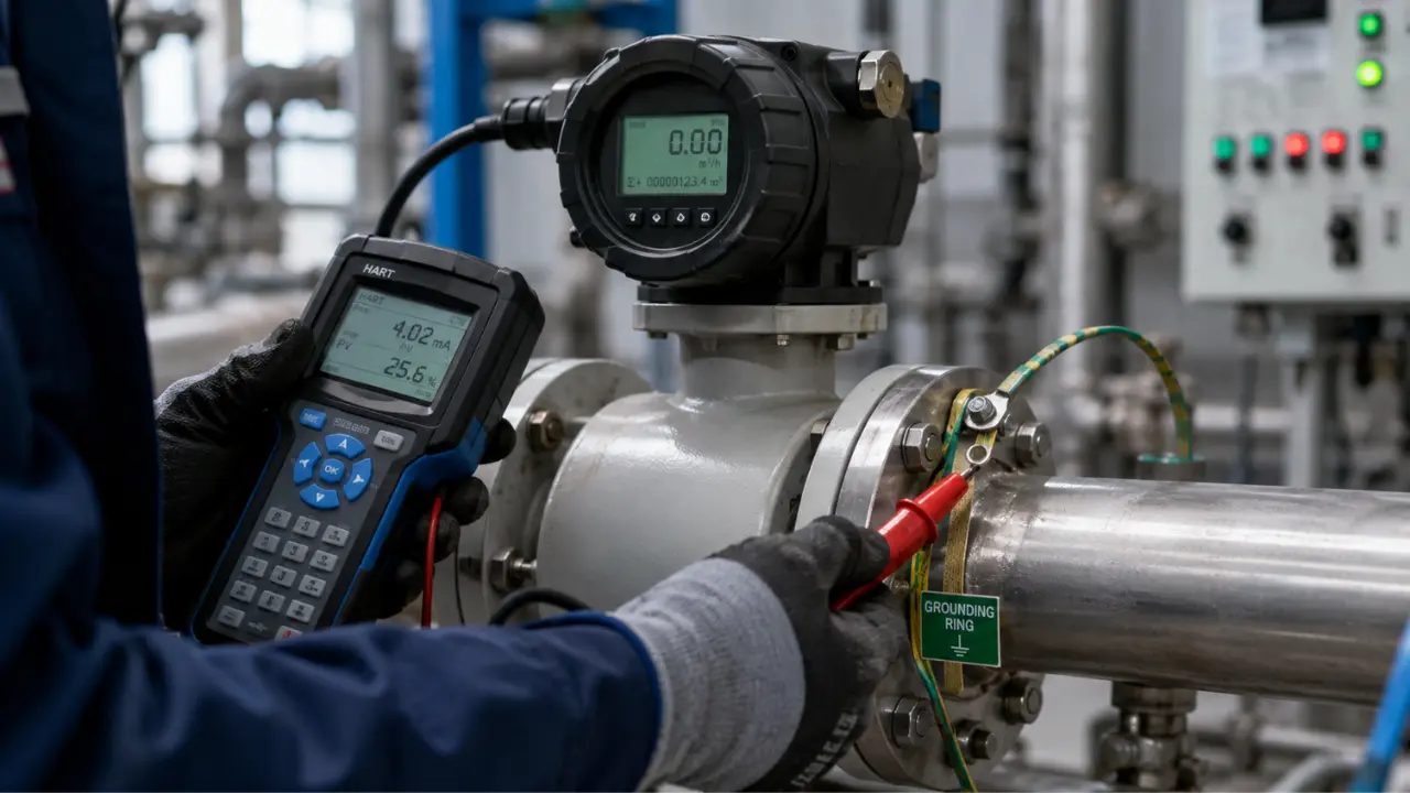
This is the failure mode behind the most confused service calls. A magmeter needs a stable reference potential between the process fluid and the transmitter electronics. On metallic, unlined pipe, that reference comes through the pipe wall itself. On lined or non-conductive pipe, there's no electrical path from the fluid to earth unless grounding rings or electrodes are installed and properly bonded. Skip that step, or let the bonding conductor corrode or loosen, and the reference floats: noisy readings, unexplained spikes, and in some geometries, apparent negative flow on a line that is unambiguously moving forward. Ground loop impedance should read below roughly 10 ohms; anything higher points at a bad or missing ground path before anything else gets replaced. It's the first thing our instrumentation and control team checks.
Ultrasonic Flowmeter Failures
An ultrasonic flowmeter measures flow by timing acoustic pulses sent upstream and downstream between transducer pairs, calculating velocity from the transit time difference, the principle covered under ISO 12242 for liquid applications and ISO 17089 for gas. Clamp-on and wetted (in-line) versions share the same failure sensitivities, though clamp-on units add a coupling variable that in-line spool-piece meters don't have.
Transducer Misalignment
Transit-time calculation assumes a known acoustic path length and angle between transducer pairs. Move a clamp-on transducer even a few millimeters during a re-install, or let a wetted transducer shift slightly on an aging gasket, and the calculated geometry no longer matches reality. The meter keeps reporting a number; it's measuring the wrong path length against the transit time it recorded, producing an error that's often a fixed, unnoticed percentage rather than an obvious fault.
Air Entrainment and Signal-to-Noise Loss
Acoustic pulses scatter off bubbles and don't transmit cleanly through a mixed liquid-gas stream. Entrained air, whether from a leaking pump seal or turbulence at a pipe transition, degrades the signal-to-noise ratio the transmitter needs for a clean transit-time measurement. Below a certain threshold, most ultrasonic flowmeter electronics flag a low signal-strength alarm or drop the reading entirely rather than report garbage, better than a silently wrong number, but it still means lost data until someone fixes the entrainment source.
Clamp-On Coupling Gel Degradation
Clamp-on ultrasonic flowmeter transducers rely on a couplant, typically a gel or grease, to transmit acoustic energy from the transducer face into the pipe wall without an air gap. That couplant dries out over time, especially on hot pipe surfaces, outdoor installations with UV and temperature cycling, or wherever it wasn't reapplied at reinstall. As it dries, coupling efficiency drops, signal strength falls, and the meter produces intermittent dropouts long before it fails completely. Permanently bonded transducer pads and glycol- or silicone-based couplants reduce this on installations that can't go offline for gel reapplication.
Coriolis Flowmeter Failures
A Coriolis meter vibrates one or two tubes at a resonant frequency and measures the phase shift and frequency change induced by the Coriolis effect as mass moves through the tube, giving a direct mass flow reading along with density, independent of fluid conductivity or acoustic properties. ISO 10790 provides selection and installation guidance for these meters, and most field failures trace back to violating conditions that standard addresses.
Tube Coating and Erosion
Process material building up inside the tube changes its effective vibrating mass, which shifts the resonant frequency the meter uses to calculate density and can bias the mass flow reading. Erosive slurries do the opposite: they wear the tube wall thinner, again changing the vibrating mass and, at worst, threatening tube integrity. Neither announces itself with an alarm until the drift is already logged, which is why periodic zero and density verification matters more here than the manufacturer's default interval assumes.
Zero Drift From Mounting Stress
Coriolis tubes are precision-balanced mechanical structures, and piping strain transmitted into the meter body through rigid mounting or misaligned flanges shifts the mechanical zero point the meter was calibrated against, producing a non-zero reading under genuinely zero-flow, full-pipe conditions. The fix is mechanical: support the meter body independently, use flexible connections where thermal expansion is a factor, and re-zero after any piping work near the meter, not just at commissioning.
Two-Phase Flow
The Coriolis measurement principle assumes a homogeneous single-phase fluid. Entrained gas in a liquid stream, or slugging flow, damps the tube's oscillation unevenly and produces erratic density and mass flow output that can look like electronic noise but is a real physical limitation of the technology, not a fault to troubleshoot electrically.
Vortex Flowmeter Failures
Vortex meters infer velocity from the frequency of vortices shed behind a bluff body, a relationship that holds across liquids, gases, and steam using the same principle, which makes them versatile but sensitive to two specific field conditions.
Flow Profile Disturbance From Inadequate Straight Run
Vortex shedding assumes a reasonably developed, symmetric flow profile approaching the bluff body. Elbows, reducers, control valves, and other fittings close upstream distort that profile and disturb shedding frequency, producing readings that are unstable or biased even though nothing on the meter has failed. Manufacturer guidance typically calls for 15 to 40 pipe diameters of straight run upstream, depending on the fitting type and how many planes it introduces, with control valves and regulators at the high end. A meter that reads fine on a bench test and unstable in the field almost always has a straight-run problem, not an electronics problem.
Low-Flow Cutoff
Vortex shedding only becomes stable and repeatable once flow reaches a Reynolds number of roughly 10,000. Below that threshold, shedding is irregular and the meter's electronics clamp the output to zero rather than report an unreliable number, which is correct behavior but gets mistaken for a dead meter on lines that spend significant time at low flow. Size the meter against actual operating flow, not just design flow, to avoid parking the process below its usable range for most of its service life.
Turbine and Mechanical Flowmeter Failures
Turbine meters and other mechanical flowmeter types measure flow through a rotor spinning proportionally to fluid velocity, so their failures are mechanical wear failures more than electronic ones.
Bearing Wear
Rotor bearings, whether ball or sleeve type, wear gradually under normal service, and as friction increases the rotor under-registers flow, most noticeably at the low end of the range where it has the least torque to overcome added drag. Left unaddressed, wear progresses to seizure. Periodic pull-and-inspect on a defined interval, rather than waiting for a discrepancy to show up in a mass balance, is the only real mitigation.
Particulate Damage
Abrasive solids in the flow stream score bearing surfaces and rotor blades directly, accelerating wear far beyond clean service and sometimes causing outright rotor damage. Correctly sized upstream strainers, not installed as a formality, are the standard mitigation, along with matching wetted materials to actual particulate loading rather than the nominal fluid specification. Our flow instrumentation services team sizes both.
Installation Errors That Outlast Commissioning
A meter installed correctly at commissioning doesn't necessarily stay installed correctly. Piping gets modified during a plant expansion, or a spool piece gets swapped and reinstalled slightly off-axis. None of that shows up on an as-built drawing, and from the control room it looks like an instrument problem, not an installation problem.
Orientation matters as much as straight run. Electromagnetic flowmeters on partially full lines need vertical, upward-flow orientation to guarantee a full bore at the measurement point. Ultrasonic flowmeter transducer pairs need the specific clock-position geometry they were configured for, not just "somewhere on the pipe." If you're revisiting flowmeter types for a new installation, working through flowmeter types and their installation constraints before ordering saves a rework cycle after the meter is welded into a spool piece. Check the installation before condemning the meter: orientation and straight-run errors outnumber instrument failures on most service calls.
Wiring, Grounding, and EMI Issues
Signal wiring problems produce symptoms that look like instrument drift or noise, sending technicians chasing the wrong root cause. Shielded twisted-pair cable, grounded at one end only, is standard practice for 4 to 20 mA and HART signal runs: ground the shield at both ends and you create a ground loop that injects noise into the signal. Routing flowmeter signal cable in the same tray as VFD power cables is a second common source, since drive switching frequencies inject electromagnetic interference that a poorly separated pair picks up. If your flowmeter output is noisy in a pattern that correlates with a nearby drive starting or stopping, check the wiring architecture first, not the transmitter. Our guide on 4-20mA, HART, and Foundation Fieldbus covers the wiring practices that prevent this class of problem before it starts.
Calibration Drift and Verification Cadence
Every flowmeter technology drifts over its service life, through different mechanisms: electromagnetic flowmeter drift from electrode wear or coating changing the signal path, Coriolis drift from tube mass changes through coating or erosion, turbine drift from bearing wear changing rotor response. None of it announces itself on the display; it accumulates until a mass balance discrepancy or a proving run exposes it.
Flowmeter calibration cadence should be driven by service severity, not a blanket schedule. General process control measurements on clean, non-erosive service can often run on a 12 to 24 month re-verification interval. Custody transfer and fiscal metering, particularly in oil and gas, are governed by API MPMS Chapter 4, which sets proving requirements on a much tighter interval than a general process instrument, often tied to volume thresholds rather than convenience. Flowmeter calibration performed at a facility accredited to ISO/IEC 17025 provides traceability documentation custody transfer applications require, a meaningfully different deliverable than a field check against a second meter.
Calibration drift on a flowmeter is rarely dramatic. It's a slow, unannounced departure from truth that a fixed verification schedule catches and a "probably fine" assumption never does.
Flow measurement drift compounds with pressure measurement drift in the same loop more often than plants expect, since the two instruments frequently feed the same control strategy or custody calculation. It's worth reviewing what actually drifts in a pressure transmitter calibration cycle alongside your flow verification schedule, since the drift mechanisms and the discipline required are closely related.
Failure Mode Quick Reference
| Flowmeter Type | Most Common Field Failure | Fix / Mitigation |
|---|---|---|
| Electromagnetic / Magnetic | Electrode coating or fouling | Monitor electrode impedance; inspect/clean electrodes; consider self-cleaning or insertion electrodes |
| Electromagnetic / Magnetic | Missing or degraded ground reference | Install grounding rings on lined/non-metallic pipe; verify bonding and ground loop impedance below ~10 ohms |
| Ultrasonic (clamp-on) | Couplant gel dries out, signal drops | Reapply couplant on schedule; switch to glycol/silicone couplant or bonded pad transducers |
| Ultrasonic (all types) | Air entrainment degrades signal-to-noise | Eliminate upstream air source; relocate meter away from turbulence and pump suction |
| Coriolis | Zero drift from piping/mounting stress | Support meter body independently; use flexible connections; re-zero after nearby piping work |
| Coriolis | Two-phase flow (entrained gas/slugging) | Eliminate gas entrainment upstream; verify process stays single-phase at the meter |
| Vortex | Unstable reading from inadequate straight run | Verify 15-40D upstream per fitting type; add flow conditioning if run is constrained |
| Vortex | Output clamps to zero at low flow | Size against actual, not design, flow range; confirm Reynolds number stays above ~10,000 |
| Turbine / Mechanical | Bearing wear causing under-registration | Scheduled pull-and-inspect; replace bearings on a defined interval, not on failure |
| Turbine / Mechanical | Particulate damage to rotor/bearings | Install correctly sized upstream strainers; match wetted materials to particulate loading |
A Real-World Scenario: Negative Flow on a Clean Water Line
A food processing plant flagged a magnetic flowmeter on a clean-in-place water line for reporting negative flow while the pump was unambiguously running forward, along with noise spikes uncorrelated to any process event. The instrument technician's first move, reasonably, was to suspect a bad transmitter and request a replacement.
Before swapping hardware, the site pulled the installation drawing and found the meter in a PTFE-lined section of pipe, spec'd correctly for the caustic cleaning cycles the line also carried. What the drawing didn't show was that the grounding rings called out in the original design had been omitted during a spool replacement two years earlier, when a contractor swapped a damaged section and reused the meter without re-bonding the ground. On lined pipe there is no metallic path from the process fluid to earth, so the meter had run on a floating reference for two years, reading acceptably by coincidence, until a nearby equipment change pushed the output into visibly erratic, apparently negative territory.
Installing grounding rings at the flanges on either side of the meter and bonding them to the transmitter's reference terminal resolved the fault within one restart. No electronics were replaced. The lesson generalizes: on lined or non-conductive pipe, a magnetic flowmeter's grounding path is part of the measurement circuit, not optional hardware, and any pipe modification near the meter has to be checked against the original grounding design.
The instrument was never broken. The measurement circuit was incomplete, and it had been incomplete for two years before anyone noticed.
Faults like this tend to resurface at the next spool swap or pipe rework. Reach out to our team before that happens on your line.
A Troubleshooting Sequence That Holds Up
When a flowmeter reading looks wrong, work the problem in this order rather than jumping straight to instrument replacement: confirm the process condition sits inside the meter's designed envelope (full pipe, conductivity, single-phase, velocity range), verify the installation still matches the commissioned straight-run and orientation requirements, check grounding and signal wiring for anything that changed, then move to electrode or transducer diagnostics, and only then to bench calibration or replacement. Most field failures resolve in the first three steps.
Flow data feeds mass balances, batch records, and often billing, so a wrong reading that goes uncaught for months is a far more expensive problem than the half-day it takes to work through this sequence properly. If you're troubleshooting a persistent flow measurement problem or building a verification schedule across a plant's instrumentation, take a look at our instrumentation and flow measurement products line or get in touch to talk through what's actually installed against what the process needs.
Related products
Components from our catalogue relevant to this article — request a quote for availability, lead time and pricing.
/Endress+Hauser 5P3B15-GRIRABEFAAED5S2AA1-Electromagnetic flowmeter.webp "Endress+Hauser 5P3B15-GRIRABEFAAED5S2AA1 Endress+Hauser - Electromagnetic Flowmeter | Electromagnetic flowmeter, Proline series")
5P3B15-GRIRABEFAAED5S2AA1 Endress+Hauser - Electromagnetic Flowmeter
Electromagnetic flowmeter, Proline series
/Endress+Hauser 5PBB1H-AAEADBKA0AED3K0AA1-Proline Promag P 10 electromagnetic flowmeter.webp "Endress+Hauser 5PBB1H-AAEADBKA0AED3K0AA1 Endress+Hauser - Proline Promag P 10 Electromagnetic Flowmeter | Proline Promag P 10 electromagnetic flowmeter")
5PBB1H-AAEADBKA0AED3K0AA1 Endress+Hauser - Proline Promag P 10 Electromagnetic Flowmeter
Proline Promag P 10 electromagnetic flowmeter
/Endress+Hauser 8F1B25-AADBBCISAFMWA+AAEBZ1-Electromagnetic flowmeter.webp "Endress+Hauser 8F1B25-AADBBCISAFMWA+AAEBZ1 Endress+Hauser - Proline Promass F 100 Coriolis Flowmeter | Coriolis mass flowmeter, DN 25, ultra-compact transmitter")
8F1B25-AADBBCISAFMWA+AAEBZ1 Endress+Hauser - Proline Promass F 100 Coriolis Flowmeter
Coriolis mass flowmeter, DN 25, ultra-compact transmitter
/Endress+Hauser 8F3B25-AAILAEAFADSAD2SBA1-Coriolis flowmeter.webp "Endress+Hauser 8F3B25-AAILAEAFADSAD2SBA1 Endress+Hauser - Proline Promass F 300 Coriolis Flowmeter DN 25 | Coriolis mass flowmeter, DN 25, compact dual-compartment transmitter")
8F3B25-AAILAEAFADSAD2SBA1 Endress+Hauser - Proline Promass F 300 Coriolis Flowmeter DN 25
Coriolis mass flowmeter, DN 25, compact dual-compartment transmitter