
Pressure Transmitter Calibration: What Actually Drifts, and How to Catch It Before It Costs You

Quick Answer
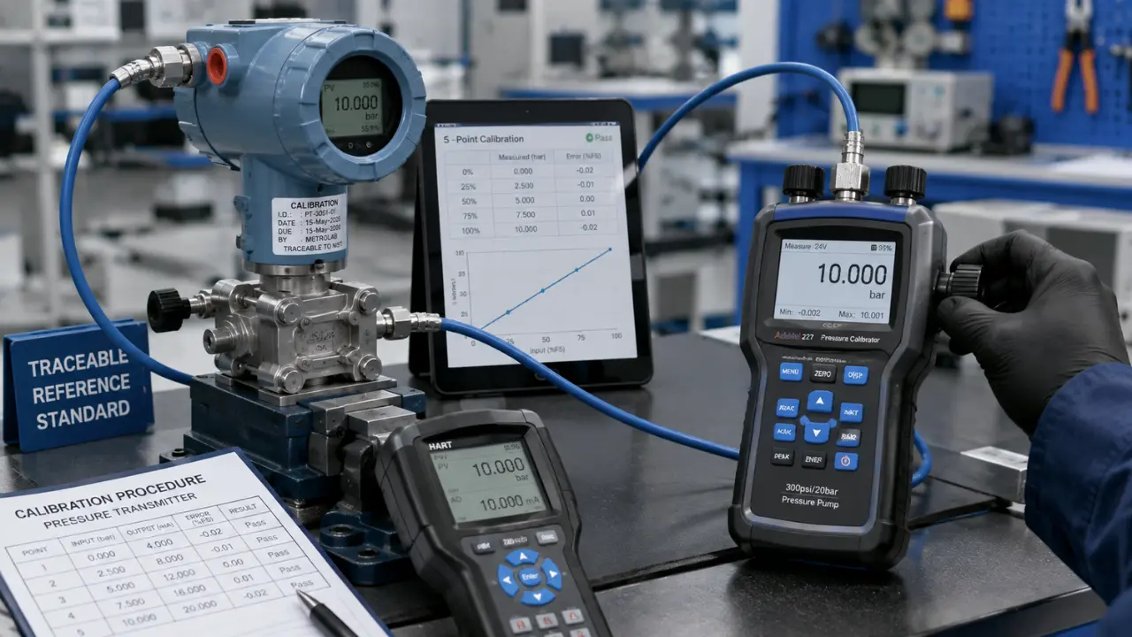
Pressure transmitter calibration means verifying output against a traceable reference standard across a 5-point span check, correcting zero and span drift separately, and documenting the result. Get the reference standard, HART trim sequence, or interval wrong, and a transmitter can pass on paper while still misleading the process.
Pressure transmitter calibration is the one maintenance task plants schedule by habit more than by evidence. A gauge transmitter on a compressor skid, an absolute transmitter on a vacuum system, and a differential pressure transmitter on a custody transfer run all get lumped into the same 12- or 24-month bucket, checked against the same generic tolerance, and rubber-stamped. That misses the point. Each transmitter type drifts for different physical reasons, at different rates, and missing it ranges from a nuisance alarm to a safety system that doesn't trip when it should.
This is a program-level look at pressure transmitter calibration across gauge, absolute, and differential pressure transmitters: what causes drift, how to verify against a traceable reference, when HART digital trim is the right tool, and how to set an interval based on real risk, not a calendar date. If you need a step-by-step answer for how to calibrate a pressure transmitter in a DP configuration, we've already published that as a dedicated field procedure guide. This post is the layer above it.
A transmitter that fails calibration is a known problem. A transmitter that's been drifting quietly for eighteen months on a blanket interval is the one that costs you.
How Pressure Transmitters Actually Drift
Every pressure transmitter has two independent error mechanisms: zero drift and span drift. Which one you're seeing determines whether a single-point zero check is enough or whether you need a full multi-point verification.
Zero Drift: The Whole Curve Shifts
Zero drift moves the entire output curve up or down without changing its slope. A transmitter reading 0.3 mbar at true zero, when it should read 0.0, carries roughly that same error across the span.
The causes differ by type. In capacitance-based DP and gauge transmitters, the silicone fill fluid that transmits pressure from the isolating diaphragms to the sensing element expands and contracts with temperature and can, over years, permeate through the diaphragm welds, shifting the baseline reading at zero. Mounting orientation matters too: a transmitter calibrated horizontally on the bench and installed vertically in the field shows a zero shift from the fill fluid's weight acting on the sensor differently. Vibration near rotating equipment accelerates mechanical settling in the sensor module and can shift zero faster than temperature alone explains. Gauge transmitters add one more path: the reference side vents to atmosphere through a port protected by a hydrophobic filter, and a filter clogged with oil mist or dust, common in compressor houses and paint booths, stops equalizing and produces a small zero error that tracks barometric changes incorrectly.
Absolute pressure transmitters have a failure mode unique to their design: the sealed reference vacuum chamber. A slow leak through a weld or a glass-to-metal seal means the reference stops being a true vacuum and zero drifts low relative to actual absolute pressure. It's undetectable without an as-found check against a dead-weight or piston gauge reference, because the output keeps looking plausible.
Span Drift: The Slope Changes
Span drift changes the relationship between applied pressure and output current, so error grows as you move away from zero. A transmitter with 1 percent span drift looks nearly correct at 10 percent of range and is meaningfully wrong at 90 percent.
Span drift is mostly an electronics and sensor-nonlinearity story: the ADC reference voltage, amplifier gain stages, and the sensor's own nonlinearity contribute small drift as components age and thermally cycle. On DP transmitters specifically, static line pressure has a direct span effect. Applying a high common-mode pressure to both sides of the sensor, say 1000 psi static line pressure on a transmitter measuring a 100 inH2O differential, stresses the sensing diaphragm and introduces span error proportional to that static pressure even though the differential is small, a mechanism manufacturers publish static pressure effect coefficients to account for. The performance gap between the Rosemount 3051 and 3051S is largely about how much better the coplanar SuperModule sensor resists it.
Reference Standards and the Test Uncertainty Ratio
You cannot make the calibration of pressure transmitter output more accurate than the standard you're comparing it against, and that gets ignored more often than it should when a technician reaches for a reference gauge that's overdue for its own calibration.
The working rule most process plants apply is a 4:1 test uncertainty ratio (TUR): the reference standard's accuracy should be at least four times better than the tolerance of the device under test. The ratio traces back to MIL-STD-45662A, the U.S. military standard that codified it in the 1980s, and it's ANSI/NCSL Z540.3, not the earlier Z540.1, that explicitly requires a minimum 4:1 TUR in a calibration program today. Modern ISO/IEC 17025:2017-accredited labs work from a documented uncertainty budget and a defined decision rule rather than a fixed number, but 4:1 remains the practical shorthand most metrology programs specify because it's simple to apply and defend in an audit. If your reference can't meet 4:1 against the transmitter's stated accuracy, get a better reference or stop calling the result a calibration.
For a field calibration of a typical process DP or gauge transmitter, a documented-accuracy portable pressure calibrator with a certificate traceable to a national metrology institute covers the requirement. Instruments like the Fluke 721, Beamex MC6, or Druck DPI 620G show up on plant calibration carts for this reason, and sourcing the right one for a given accuracy class is available through our product line. Fiscal metering and custody transfer are where the reference decision gets hardest: differential pressure transmitter calibration on a flow run feeding a billing calculation is already held to a tight tolerance, and a dead-weight tester or piston gauge is often the only reference that can still hold a 4:1 ratio against it, pushing the work into a bench or lab setting. Whatever reference is used, it needs its own current certificate, traceable through an unbroken chain to a national metrology institute per ISO/IEC 17025:2017, or the number reported means nothing to an auditor or a customer disputing a custody transfer volume.
The 5-Point Ascending/Descending Method
Any complete answer to how to calibrate a pressure transmitter in the field starts here: the accepted method for calibrating a pressure transmitter's output is a 5-point ascending and descending check. Apply pressure at 0, 25, 50, 75, and 100 percent of configured span going up, record the output at each point, then repeat it coming back down. Five points catch nonlinearity a two-point zero-and-span check would miss, and running both directions catches hysteresis, the small lag between a transmitter's response to increasing versus decreasing pressure that shows up in aging sensors more than in electronics.
What matters at a program level is the acceptance tolerance at each point, usually tied to the transmitter's published reference accuracy plus margin, and whether as-found data is captured before any adjustment. As-found data is what tells you something about process risk, because it's what the transmitter was reporting before anyone touched it. Skip that step and jump straight to adjustment, and you've thrown away the one data point that tells you whether your calibration interval is set correctly.
The complete step-by-step version, with manifold valve sequencing and specific acceptance tolerances for DP transmitters, is covered in our field-level procedure guide. The method is essentially the same for gauge and absolute units, minus the manifold equalization step, since there's no high side and low side to isolate against each other.
HART Digital Trim vs. Analog Loop Trim
This is where the calibration of pressure transmitter loops quietly goes wrong. A HART-enabled smart transmitter has at least two distinct trim operations, and they correct different things. Sensor trim (digital trim) adjusts the relationship between applied pressure and the transmitter's internal digital reading, upstream of the analog output; it corrects the sensor and its analog-to-digital conversion. D/A trim (output trim) adjusts the relationship between the digital reading and the 4-20 mA current on the wire; it corrects the digital-to-analog stage, not the sensor. Loop trim, done at the receiving end, verifies the control system reads the same current the transmitter sends, catching wiring and I/O card issues unrelated to the transmitter.
Sensor trim and D/A trim matter together because they can mask each other. A technician who only performs a D/A trim, forcing the mA output to match a reference multimeter at two points, can make a transmitter with real sensor drift look calibrated on the loop while the underlying pressure measurement stays wrong. The digital value reported over HART, what any asset management or diagnostic package reads, stays wrong even after the analog output is forced into line. It's a common field mistake, and it's why calibrating pressure transmitter loops correctly means sensor trim against a pressure reference first, D/A trim second, never the reverse.
Which trims are even relevant depends on loop architecture, a bigger question we cover in the tradeoffs between 4-20mA, HART, and Foundation Fieldbus.
Wet Leg Compensation and DP Calibration
Differential pressure transmitter calibration on a level application introduces a variable flow or gauge measurements don't have: the wet leg. When a DP transmitter measures level in a vessel with a condensable vapor space, and the low-pressure impulse line is filled with sealing fluid instead of vented to the vapor space, that column of fluid exerts a constant hydrostatic pressure on the low-pressure port.
The transmitter has to be range-configured to treat that wet leg pressure as a zero elevation, part of the baseline it subtracts out. If the fluid's density changes, from temperature swings, partial evaporation, or a maintenance refill with the wrong fluid, the elevation value no longer matches reality, and every level reading is off by a fixed amount a routine zero check won't catch unless the wet leg column and fluid condition are physically verified.
On a wet leg installation, calibrating pressure transmitter loops means confirming the physical installation still matches the configuration sheet, not just applying test pressure and reading mA output. Our differential pressure procedure guide walks through the wet leg and dry leg compensation math, including how to tell an instrument drift problem from an installation problem that only looks like drift.
Environmental and Temperature-Induced Drift
Ambient temperature swings are an underestimated drift source across every transmitter type. Manufacturers publish a temperature effect coefficient, a percent of span per fixed temperature interval, applied across the transmitter's full rated ambient range. A transmitter on an outdoor pipe rack with a 40°C swing between summer and winter, or one mounted near a furnace or steam line, sees real thermal cycling a climate-controlled instrument never does, accelerating the same mechanical fatigue and fill-fluid degradation that drives long-term zero and span drift. A transmitter in a harsh thermal environment needs a shorter interval than an identical unit in a benign one.
Moisture ingress compounds it. A damaged conduit seal or a housing gasket that's lost compression lets moisture into the electronics housing, and condensation cycling with ambient swings is a common root cause of intermittent zero shifts that don't show a clean, repeatable pattern, making them harder to catch from calibration records alone.
Drift Mechanism and Recommended Interval by Type
| Transmitter Type | Typical Drift Mechanism | Recommended Check Interval |
|---|---|---|
| Gauge pressure | Vent filter fouling, fill-fluid thermal cycling, mounting shift | 12–24 months, general service |
| Absolute pressure | Reference vacuum chamber leak (slow zero drift), electronics aging | 12–18 months, shorter for vacuum-critical processes |
| DP transmitter, flow service | Static pressure span error, primary element condition | 12 months, or per historical drift data once established |
| DP transmitter, level with wet leg | Wet leg fluid density change, zero elevation mismatch | 6–12 months, plus a physical wet leg check each visit |
| DP transmitter, custody transfer | Any of the above, held to a tighter tolerance against a dead-weight reference | 3–6 months, per contractual or regulatory requirement |
| Any type, SIS/safety loop | Same mechanisms, but proof test interval derives from target PFDavg, not drift alone | Per IEC 61511 SIF calculation, typically 3–12 months |
These are starting points, not a substitute for risk analysis: a transmitter with three consecutive clean cycles is a different risk than one that's failed as-found checks twice running.
Setting a Risk-Based Calibration Interval
A blanket interval applied uniformly across a plant is administratively easy and technically indefensible. It calibrates stable transmitters more often than necessary and, more dangerously, unstable or high-consequence ones less often than they need.
A risk-based interval starts from two inputs. First, process criticality: what happens if this transmitter is wrong and nobody knows for a while. A transmitter feeding a trend display carries a different consequence than one feeding a high-pressure trip on a reactor or acting as the sensing element in a safety instrumented function under IEC 61511. Second, historical drift data: what the as-found reading showed at the last two or three events, measured against acceptance tolerance. A transmitter consistently within a third of its tolerance band is a candidate for interval extension; one approaching or exceeding tolerance needs a shorter interval, a root cause investigation, or replacement.
For an instrument in a safety instrumented function, the interval isn't a calibration decision at all. It's a proof test interval derived from the safety integrity level target and the component's dangerous failure rate under IEC 61511, and that calculation should drive the schedule regardless of what the general plant program says. Treating a SIS-critical transmitter like a balance-of-plant utility gauge on the same fixed interval is a common process safety audit finding, and easy to fix once the criticality classification exists. Building that classification into a documented program is the work our instrumentation and control services team scopes for a plant standing up a calibration program from scratch. Environmental severity factors into both inputs too: a high-vibration or high-thermal-cycling location earns a shorter interval before any drift history even exists.
Documentation and Traceability Expectations
Pressure transmitter calibration that isn't documented might as well not have happened. There's no way to prove it later, or build the drift history a risk-based interval depends on. At minimum, a defensible record includes the tag number and range configuration, the reference standard and its certificate number, as-found data at all five points in both directions, any adjustment made, as-left data confirming the correction, the technician's identification, and the date, tracing back through an unbroken chain to a national metrology institute consistent with ISO/IEC 17025:2017.
A CMMS platform like SAP PM or Maximo can automate most of this and build the drift trend automatically. A paper-based program can do the same, but only as deliberate practice, not something pulled together the week an auditor asks for it.
A Real-World Scenario: The Interval That Wasn't Really Set
A mid-sized specialty chemical plant ran a gauge pressure transmitter on a reactor's nitrogen blanket system, tied into a high-pressure interlock that would trip a vent valve if headspace pressure exceeded a safe threshold. The transmitter sat on the plant's standard 24-month schedule, the same interval applied to nearly every non-flow pressure instrument on site, inherited from the original commissioning spec and never revisited.
Mounted directly above the reactor, it picked up radiant heat during batch cycles that ran hot for hours, several times a week. Over roughly 20 months, that cycling combined with a fouling vent filter produced a span drift that left it reading about 3 percent low at the upper end of its range. Nobody caught it: the reading still looked plausible on the DCS trend, and the interlock never tripped, because normal operation never approached the setpoint closely enough to expose the error.
The drift surfaced at the next scheduled calibration, during a turnaround, when the as-found check showed an error nearly three times the acceptance tolerance at the 75 and 100 percent points. That transmitter had under-reported actual headspace pressure for the better part of two years, meaning the safety margin to the interlock trip point had been quietly shrinking, with no alarm and no indication anything was wrong.
The plant's response wasn't just to recalibrate and move on. The team reclassified every transmitter feeding a safety interlock or high-consequence trip, shortened the interval for anything in a high-thermal-cycling location, and started tracking as-found drift by tag number instead of blanket schedule. The transmitter wasn't defective. The interval was never calculated against risk; it was inherited, and that's what let the drift run unnoticed as long as it did.
A calibration interval that was never actually calculated against risk isn't conservative. It's a guess that happens to look official on a schedule.
Where This Fits Into a Broader Instrumentation Program
The same mechanisms, thermal cycling, static pressure effects, sensor aging, apply whether a transmitter feeds a standalone gauge reading or acts as the primary element input to a flow calculation, and a transmitter that's technically correct but feeding a flow meter with its own accuracy problem still produces a bad flow number. If a flow measurement won't hold its numbers, check whether the root cause sits upstream at the transmitter or downstream in the primary element and meter condition before assuming either component is at fault.
Getting a calibration program right, reference standards that actually meet 4:1, a documented risk-based interval instead of an inherited default, and HART trim sequencing that corrects the sensor before the output, takes more upfront engineering than running everything on the same calendar date. It's also the difference between a transmitter you can defend in an audit and one you're hoping nobody questions. Techno Control Corporation supports plants across process, power, and manufacturing sectors with transmitter and reference-standard sourcing, traceable field calibration, and risk-based interval programs built from scratch. If your calibration schedule was inherited rather than calculated, get in touch and we'll walk through what your transmitter population actually needs.
Related products
Components from our catalogue relevant to this article — request a quote for availability, lead time and pricing.
/Endress+Hauser 5P3B15-GRIRABEFAAED5S2AA1-Electromagnetic flowmeter.webp "Endress+Hauser 5P3B15-GRIRABEFAAED5S2AA1 Endress+Hauser - Electromagnetic Flowmeter | Electromagnetic flowmeter, Proline series")
5P3B15-GRIRABEFAAED5S2AA1 Endress+Hauser - Electromagnetic Flowmeter
Electromagnetic flowmeter, Proline series
/Endress+Hauser 5PBB1H-AAEADBKA0AED3K0AA1-Proline Promag P 10 electromagnetic flowmeter.webp "Endress+Hauser 5PBB1H-AAEADBKA0AED3K0AA1 Endress+Hauser - Proline Promag P 10 Electromagnetic Flowmeter | Proline Promag P 10 electromagnetic flowmeter")
5PBB1H-AAEADBKA0AED3K0AA1 Endress+Hauser - Proline Promag P 10 Electromagnetic Flowmeter
Proline Promag P 10 electromagnetic flowmeter
/Endress+Hauser CLD134-PCS138AB2-Non-contact conductivity sensor.webp "Endress+Hauser CLD134-PCS138AB2 Endress+Hauser - Non-Contact Conductivity Sensor | Inductive non-contact conductivity sensor")
CLD134-PCS138AB2 Endress+Hauser - Non-Contact Conductivity Sensor
Inductive non-contact conductivity sensor
/Endress+Hauser COS61D-AAA1A4-Digital oxygen measurement sensor.webp "Endress+Hauser COS61D-AAA1A4 Endress+Hauser - Digital Oxygen Measurement Sensor | Digital dissolved oxygen sensor")
COS61D-AAA1A4 Endress+Hauser - Digital Oxygen Measurement Sensor
Digital dissolved oxygen sensor