
Clamp-On Ultrasonic Flow Meters: Where Transit-Time Works and Where It Lies

Quick Answer
An ultrasonic flow meter times sound pulses between transducers to measure flow, and clamp-on versions do it without cutting into the pipe, but transit-time accuracy collapses on lined, scaled, or fibreglass pipe unless the installation is verified first.
An ultrasonic flow meter measures liquid or gas velocity by timing acoustic pulses between transducers, and a clamp-on version does it without touching the process fluid: strap two transducers onto an existing pipe and get a reading in minutes. That's genuinely useful, and also the most oversold instrument in a plant engineer's toolkit. Transit-time physics works exactly as advertised on a clean, single-phase liquid in a known, unlined, reasonably straight pipe. Move that same clamp-on ultrasonic flow meter onto a cement-mortar-lined water main, a heavily scaled condensate line, or a fibreglass seawater intake, and the transit-time principle that made it attractive stops applying, often without any warning on the display. This guide stays inside ultrasonic measurement: where transit-time earns its reputation, where Doppler solves a different problem, and how to verify a reading before anyone treats it as fact.
How Does an Ultrasonic Flow Meter Work?
A transit-time ultrasonic flow meter times a sound pulse fired with the flow against one fired against it. Sound moving with the flow arrives fractionally sooner, and that difference converts directly into velocity, then into a volumetric flow rate once pipe geometry is factored in.
The Ultrasonic Flow Meter Working Principle, in Plain Terms
The ultrasonic flow meter working principle behind transit-time measurement is simpler than the electronics suggest. Two transducers sit on a diagonal chord across the pipe, angled through a wedge so the beam refracts into the fluid at a known angle, and the processor times pulses fired in both directions. That difference has a convenient mathematical property: the fluid's own speed of sound cancels out of the velocity equation entirely, so a transit-time meter moves from water to diesel to glycol without a fresh calibration curve for each fluid.
What it can't get around is geometry. Converting a timing difference into velocity requires the exact acoustic path length and refraction angle through the pipe wall, and getting the pipe's outside diameter, wall thickness, or wall material wrong at setup still produces a confident, stable number, just computed against the wrong path length. These meters feed directly into the PLC and SCADA layers of most industrial automation systems, so a wrong flow signal doesn't stay isolated.
Doppler: A Different Measurement Entirely
Transit-time and Doppler measurement aren't variations on one idea; they measure different physical events and need opposite fluid conditions to work at all. A Doppler ultrasonic flow meter transmits continuously into the pipe and listens for sound reflected off something moving with the fluid, typically suspended solids or entrained gas bubbles, then measures the frequency shift between the transmitted and reflected signal, proportional to the reflector's velocity.
That single choice flips every requirement transit-time depends on: transit-time needs a clean, single-phase fluid, since anything that scatters the beam degrades the timing it relies on, while a Doppler ultrasonic flow meter needs a minimum concentration of reflectors, cited at roughly 100 ppm of particles or bubbles 100 microns or larger, or it produces no reading.
Accuracy tracks that trade-off. Transit-time meters are specified as a percentage of reading; Doppler units are usually specified as a percentage of full scale, commonly 2 percent or worse, which behaves very differently across a turndown range. A Doppler ultrasonic flow meter suits slurries, raw wastewater, and aerated streams where nothing else will clamp on and read, not a substitute for transit-time measurement on a clean liquid.
Clamp-On vs Wetted: Two Ways to Put the Transducers on the Pipe
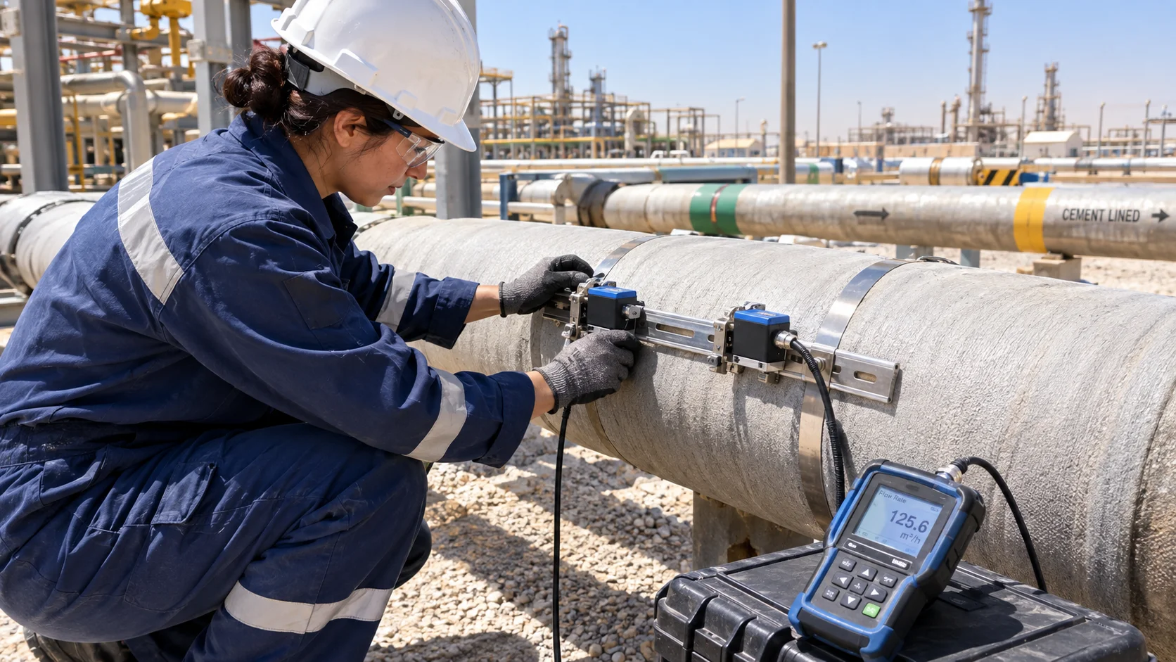
A clamp-on ultrasonic flow meter mounts its transducers on the outside of an existing pipe, coupling sound through the pipe wall via a wedge and a couplant layer. A wetted, or in-line, meter carries the same class of transducers on a spool piece welded or flanged into the line, in direct contact with the fluid. Both run identical transit-time mathematics; the difference is how reliably the signal gets from transducer into fluid and back without a wall, liner, or coupling layer in the way.
That's why clamp-on units dominate two use cases: portable verification and permanent installation on pipe nobody wants to cut into. A portable ultrasonic flow meter, wheeled from line to line on a plant-wide survey, lets one technician spot-check dozens of lines in a shift without a hot-work permit. Municipal water utilities rely on this constantly: an ultrasonic water flow meter clamped onto a distribution main is often the fastest way to check a suspect reading without excavating a road. Neither configuration matches a wetted multi-path meter's accuracy class, a distinction the broader flowmeter selection guide covers more fully.
Where the Numbers Actually Go Wrong: Sound Velocity and Wall Thickness
Every clamp-on ultrasonic flow meter setup starts with a technician entering pipe outside diameter, wall thickness, pipe material, and expected sound velocity into the transmitter; those four numbers fix transducer spacing and beam refraction angle before a reading means anything.
Wall thickness is the number most often taken from a drawing instead of the pipe itself, and it's the number corrosion moves the most. Actual wall thickness on an in-service line commonly deviates 1 to 3 mm from nominal schedule data, and since that figure sets both the beam's refraction angle and the transducer spacing, a small wall-thickness error produces a disproportionately larger spacing error, a fixed bias set at commissioning that won't average out no matter how long the meter runs. Measuring actual OD and wall thickness with a UT gauge at the mounting point, not the piping isometric, is the cheapest accuracy improvement on a clamp-on ultrasonic flow meter installation.
Sound velocity works the opposite way: it cancels out of the core flow equation, so it doesn't need to be known precisely, but it's one of the best diagnostic numbers the meter exposes. Water at 20°C should read close to 1,482 m/s; light hydrocarbons sit in the 1,300 to 1,400 m/s range. A displayed value that drifts outside that window signals a wrong fluid assumption, entrained gas, or a signal that isn't locking onto the path it thinks it is.
Pipe Wall and Liner Materials That Break Clamp-On Readings
Transit-time measurement depends on sound crossing the pipe wall cleanly in both directions. Several pipe constructions common on real sites interfere with that path badly enough to invalidate a clamp-on ultrasonic flow meter reading entirely, not just degrade it.
Cement-mortar-lined ductile iron and concrete-lined pipe, standard on large water, firewater, and cooling-water lines, scatter the beam at both the lining-to-metal and lining-to-fluid interfaces. Plastic-lined pipe, common in corrosive chemical service, does the same: the impedance mismatch between liner and steel puts a bare-steel-calibrated transducer onto the wrong material outright. Heavily scaled pipe, typical on hard-water loops and aging condensate lines, adds an uncontrolled third layer to a calculation built for exactly two. Fibreglass-reinforced (GRP/FRP) pipe is the worst case: its resin-and-glass-fibre structure scatters or attenuates the signal so severely that a standard clamp-on transducer either finds no usable signal, or holds a stable-looking reading that runs meaningfully off actual flow, with no way to tell from the display.
A clamp-on ultrasonic flow meter that finds a signal is not the same as a clamp-on ultrasonic flow meter that found the right path through the pipe.
Manufacturers build lower-frequency, larger-aperture transducers for GRP and lined pipe; read the pipe specification before the transducer datasheet.
Couplant, Ambient Heat, and Why Gulf Installations Fail Differently
A clamp-on transducer transmits sound into the pipe wall through a couplant layer, typically a gel or grease, that eliminates the air gap between transducer face and pipe; air alone reflects nearly the entire signal, so no couplant means no reading. Standard piezoelectric transducers are rated for roughly 80°C of continuous surface contact, and the glycol- or glycerin-based couplants paired with them start drying out near 100°C. High-temperature variants, built around ceramic or lithium-niobate elements with an extended acoustic delay line, push that to roughly 200°C with a high-temperature couplant paste rated higher still.
That matters more across the Gulf than a generic datasheet implies. Ambient summer temperatures of 45 to 50°C across the UAE, Saudi Arabia, Qatar, and Oman routinely push exposed, unshaded process piping past standard couplant limits before the process fluid contributes any heat at all, and outdoor installations add daily thermal cycling on top. A couplant that lasts years indoors in a temperate climate can dry, crack, or debond within months on a sun-exposed line outside Dammam or Dubai. The failure is rarely a hard fault; it's a slow drop in signal strength producing intermittent dropouts long before the meter stops reporting a number. The coupling-gel and wall-thickness failures above overlap with "Clamp-On Coupling Gel Degradation" and "Transducer Misalignment" in our flowmeter troubleshooting guide, covered there generally; the added depth here is Gulf-specific ambient thresholds and a commissioning-stage, not mechanical, cause.
Straight-Run and Installation Geometry
Transit-time accuracy assumes a symmetric velocity profile, the reason straight-run requirements exist at all. The conventional baseline for a clamp-on ultrasonic flow meter is 10 pipe diameters upstream of the transducers and 5 downstream. Two elbows in different planes, common wherever piping changes both direction and elevation, introduce a swirl a straight-run allowance alone doesn't correct, pushing the upstream figure to 15 or 20 diameters; a valve or pump immediately downstream extends the downstream allowance to roughly 10. A meter mounted four diameters downstream of a throttled valve reads a distorted profile no single-path geometry can average out, however stable it looks.
How Accurate Are Clamp-On Flow Meters, Really?
How accurate a clamp-on flow meter is depends on which configuration the question is really asking about, and treating them as one accuracy class is where most disappointment starts. A well-installed clamp-on ultrasonic flow meter, on known bare metal pipe with verified wall thickness and adequate straight run, typically delivers 1 to 3 percent of reading in real field conditions. A wetted, multi-path meter installed as a permanent spool piece, still uncalibrated against a flow standard, typically improves that to roughly 0.5 to 1 percent, simply by removing the pipe wall, coupling, and lining variables. Send that meter through a flow calibration or proving run, the step fiscal metering requires, and uncertainty commonly drops to 0.1-0.15 percent, the range where custody-transfer specifications live.
Path count partly explains why the wetted multi-path number improves so much. A single- or dual-path meter measures velocity along one or two chords and assumes the rest of the profile follows a known shape; a multi-path meter, integrating four, six, or more chords with a weighted scheme, measures more of the actual profile directly, holding accuracy through swirl that would bias a single-path reading. Six-path Gauss-Legendre integration is among the most widely deployed configurations for that reason, though transducer quality, meter-body geometry, and calibration matter just as much as path count.
| Configuration | Typical Accuracy | Fluid Requirement | Accepted for Custody Transfer? | Governing Standard |
|---|---|---|---|---|
| Doppler, clamp-on | 2-5% of full scale | Particles/bubbles, ~100 ppm | No | None (indicator-grade) |
| Transit-time, clamp-on | 1-3% of reading | Clean, single-phase, known pipe | No | ISO 12242 (install/performance) |
| Transit-time, wetted multi-path (uncalibrated) | 0.5-1% of reading | Clean, single-phase | Allocation/check-metering only | ISO 12242 / API MPMS Ch. 5.8 |
| Transit-time, wetted multi-path (proven, liquid) | 0.1-0.15% of reading | Clean, single-phase | Yes | API MPMS Chapter 5.8 |
| Transit-time, wetted multi-path (proven, gas) | 0.1-0.2% of reading | Clean, single-phase gas | Yes | AGA Report No. 9 / ISO 17089-1 |
Can a Clamp-On Meter Be Used for Custody Transfer?
No, not on its own, and the governing standard says so explicitly. API MPMS Chapter 5.8, covering ultrasonic measurement of liquid hydrocarbons for custody transfer, allocation, check-metering, and leak detection, scopes itself to spool-type, multi-path meters with permanently affixed transducer assemblies. A clamp-on meter isn't that instrument, however carefully installed, and can't be retrofitted into the role by setup alone.
ISO 12242 does cover clamp-on configurations, but as an installation and performance standard, not a custody-transfer mandate: it explains how to specify a clamp-on ultrasonic flow meter correctly, not that doing so qualifies for fiscal measurement. OIML R 117, the legal-metrology standard for liquids other than water, permits ultrasonic technology broadly, but through type-approved, permanently installed instruments, not a portable unit moved line to line.
A clamp-on reading and a custody-transfer-grade reading can look identical on a transmitter screen and mean two completely different things the moment either one ends up in a contract dispute.
That leaves a narrower role for clamp-on measurement around custody transfer without being custody transfer: check-metering against a certified fiscal meter, leak-detection screening, and allocation estimates where a wetted meter was never installed. Presenting a clamp-on reading as equivalent to a certified custody-transfer number, in a cost-allocation dispute between business units, is a documented way to lose the argument.
Ultrasonic Gas Flow Meters: A Different Reliability Picture Than Liquid
An ultrasonic gas flow meter faces a physics problem clamp-on liquid measurement doesn't: gas is roughly three orders of magnitude less dense than liquid, so far less acoustic energy couples from a clamp-on transducer through a steel wall into the gas. Clamp-on ultrasonic gas measurement exists, mostly on large, low-pressure ducts and stack-flow work, but remains a niche case with lower confidence than clamp-on liquid measurement.
Virtually all serious ultrasonic gas flow meter work in custody-transfer service uses wetted, multi-path spool meters instead, governed by AGA Report No. 9 (3rd edition, 2017) for fiscal measurement and by ISO 17089-1 for custody transfer and allocation, with ISO 17089-2 covering industrial, non-fiscal gas metering under lighter requirements. These meters dominate gas custody transfer because they have no moving parts to wear, hold calibration longer than a turbine or orifice meter, and, with four to eight or more acoustic paths, integrate a gas velocity profile accurately enough to meet AGA Report No. 9's tight uncertainty bands. None of that transfers to a clamp-on unit strapped onto a gas line for a quick check; treat that reading as a rough indicator, not a number to build an energy balance on.
A Real-World Scenario: The Chilled-Water Line That Read Wrong With a Straight Face
A district cooling plant supplying a mixed-use development in the Gulf needed a quick flow check on one building's chilled-water loop while the primary electromagnetic flowmeter's isolation valve was out for an actuator replacement. The site team clamped a portable ultrasonic flow meter onto an accessible straight section of the DN600 supply main to track delivered flow during the two-day outage. Chilled-water networks are exactly where an ultrasonic water flow meter earns its non-intrusive reputation, and exactly where pipe lining catches people out.
The unit acquired a signal within minutes and displayed a stable, plausible flow rate for the rest of the job. Signal strength sat comfortably above the alarm threshold, so nobody questioned it. Only afterward, reconciling the logged data against the building's independent energy sub-meter, did the numbers stop agreeing: the clamp-on log implied close to 30 percent less flow than the sub-meter's record for the same period.
The root cause traced back to the pipe, not the meter: the DN600 main was cement-mortar-lined ductile iron, standard for that size and service, and nobody had checked the lining before choosing a mounting position or transducer type. The generic transducer set was coupling into a lining layer it was never configured for, producing a stable but wrong path-length assumption instead of an obvious dropout.
The meter never reported a fault. It reported a wrong number with exactly the same confidence as a right one, which is the entire danger of trusting a clamp-on reading that was never checked against the pipe it was mounted on.
The fix was procedural: check the as-built pipe specification for lining and material before every clamp-on mounting, and where lining can't be avoided, either expose a short bare-metal test spool or specify transducers built for lined pipe.
Field Verification: Confirming a Reading Before Anyone Relies on It
None of the failure modes above are reasons to avoid clamp-on ultrasonic measurement. They're reasons to verify a reading before treating it as fact, exactly the field verification work our instrumentation and control team runs before a client acts on a flow number.
Start with the pipe, not the meter: confirm actual OD and wall thickness with a UT gauge at the mounting point, and confirm lining or scale condition from the as-built specification, not the drawing. Enter the correct pipe and liner material instead of defaulting to bare steel. Check the displayed sound velocity against the expected value for the actual fluid and temperature, not just flow rate, and treat any meaningful deviation as a reason to stop before logging data. Confirm the installation has the straight run the configuration assumes, or relocate the transducers or apply the manufacturer's correction factor.
Where the reading actually matters, mount at two clock positions or a second independent path and confirm they agree before trusting either, and run the meter in parallel against a reference standard first. That's where a clamp on ultrasonic flow meter earns its keep: not a replacement for a properly specified permanent meter, but a fast, non-intrusive way to find out what a line is actually doing, provided someone checks the pipe it's clamped to first.
Getting a clamp on ultrasonic flow meter reading right comes down to the same discipline behind any field instrumentation decision: know the pipe, know the fluid, and verify the number against something independent before a plant acts on it. It's worth building into a broader electrical and instrumentation reliability program rather than treating any single flow check as a one-off. If a reading doesn't reconcile with a mass balance or a billing dispute, or you're specifying flow measurement for a new line, get in touch with your process data and we'll help match the technology, and the standard, to what the application needs.
Frequently Asked Questions
How does an ultrasonic flow meter work?
A transit-time ultrasonic flow meter fires sound pulses in both directions across a pipe and times the difference between them; sound moving with the flow arrives fractionally sooner, and that difference converts to velocity once the pipe's exact geometry is known. Get the pipe's wall thickness or material wrong at setup and the meter still gives a confident, stable, wrong number.
What is the difference between transit-time and Doppler ultrasonic meters?
Transit-time needs a clean, single-phase fluid, because anything that scatters the beam degrades the timing measurement it depends on. A Doppler ultrasonic flow meter needs the opposite: a minimum concentration of particles or bubbles to reflect sound off, making it the right choice for slurries and aerated streams rather than clean liquids.
How accurate are clamp-on flow meters, really?
A well-installed clamp-on unit on known pipe with adequate straight run typically delivers 1 to 3 percent of reading in the field. A wetted, multi-path meter installed as a permanent spool piece improves on that to roughly 0.5 to 1 percent, and only a calibrated, proven meter reaches the 0.1 to 0.15 percent range custody transfer requires.
Can a clamp-on meter be used for custody transfer?
No. API MPMS Chapter 5.8 scopes custody-transfer ultrasonic metering to spool-type, multi-path meters with permanently affixed transducers, not clamp-on units. A clamp-on meter still has real value for check-metering and leak-detection screening, just not as a substitute for a certified fiscal meter.
Related products
Components from our catalogue relevant to this article — request a quote for availability, lead time and pricing.
/Endress+Hauser 5P3B15-GRIRABEFAAED5S2AA1-Electromagnetic flowmeter.webp "Endress+Hauser 5P3B15-GRIRABEFAAED5S2AA1 Endress+Hauser - Electromagnetic Flowmeter | Electromagnetic flowmeter, Proline series")
5P3B15-GRIRABEFAAED5S2AA1 Endress+Hauser - Electromagnetic Flowmeter
Electromagnetic flowmeter, Proline series
/Endress+Hauser 5PBB1H-AAEADBKA0AED3K0AA1-Proline Promag P 10 electromagnetic flowmeter.webp "Endress+Hauser 5PBB1H-AAEADBKA0AED3K0AA1 Endress+Hauser - Proline Promag P 10 Electromagnetic Flowmeter | Proline Promag P 10 electromagnetic flowmeter")
5PBB1H-AAEADBKA0AED3K0AA1 Endress+Hauser - Proline Promag P 10 Electromagnetic Flowmeter
Proline Promag P 10 electromagnetic flowmeter
/Endress+Hauser CLD134-PCS138AB2-Non-contact conductivity sensor.webp "Endress+Hauser CLD134-PCS138AB2 Endress+Hauser - Non-Contact Conductivity Sensor | Inductive non-contact conductivity sensor")
CLD134-PCS138AB2 Endress+Hauser - Non-Contact Conductivity Sensor
Inductive non-contact conductivity sensor
/Endress+Hauser COS61D-AAA1A4-Digital oxygen measurement sensor.webp "Endress+Hauser COS61D-AAA1A4 Endress+Hauser - Digital Oxygen Measurement Sensor | Digital dissolved oxygen sensor")
COS61D-AAA1A4 Endress+Hauser - Digital Oxygen Measurement Sensor
Digital dissolved oxygen sensor