
High Power VFD Systems: Where a 500 kW Enclosed Altivar ATV960 Earns Its Price

Quick Answer
A high power VFD above 250 kW is a different purchase from a standard drive: cabinet, cooling, harmonics and bypass all need specifying. Here is where a 500 kW Altivar ATV960 enclosed drive system earns its price.
A drive for a 7.5 kW pump arrives in a box and is wired up in an afternoon. A drive for a 450 kW pump arrives on a truck, needs a crane or a forklift, takes a day to bring through the door, and has to be fed by cables as thick as a forearm, cooled by a room's worth of air and cleared by the utility for the harmonics it sends back. Specifying it like a larger version of the small one is how projects end up with an overheating cabinet, a failed harmonic study or a cable that does not fit the terminals.
A high power VFD is a variable frequency drive for motors above roughly 250 kW at low voltage, up to the point where medium voltage takes over near 1 MW. At that size the drive is bought as a system: power section, enclosure, cooling, input protection, line reactors and communications, with options for bypass and braking. This guide explains where an enclosed drive system makes sense, how to read the ratings of a 500 kW VFD such as the Schneider Altivar Process ATV960, how to size the drive against the motor, what the heat and harmonics are, how bypass and safety work, and where the energy savings justify the price, with a 400 V VFD example for large pumps and fans.
What Counts as High Power, and Why the Purchase Changes
There is no sharp line, but several things change together as a drive passes a few hundred kilowatts. The current reaches the high hundreds of amperes, so busbars replace cables inside the drive and cable runs need multiple conductors per phase. The losses, even at 98 percent efficiency, become a heat load of several kilowatts that a room must carry away. The harmonic currents are large enough to matter to the transformer and the supply authority. And the cost of a failure is a stopped pump station or a stopped fan on a boiler, not a swapped small unit.
Above about 1 MW, most plants move to medium voltage drives, which run at 3.3 to 11 kV and need their own transformers and rooms; our guide to medium voltage motor VFD panel selection covers that range. Between 250 kW and 1 MW, a low voltage drive, usually a 400 V VFD or a 690 V one, dominates, and the choice is between building the drive into a custom panel and buying a factory-assembled system.
Enclosed Drive System or a Drive Module in a Custom Panel
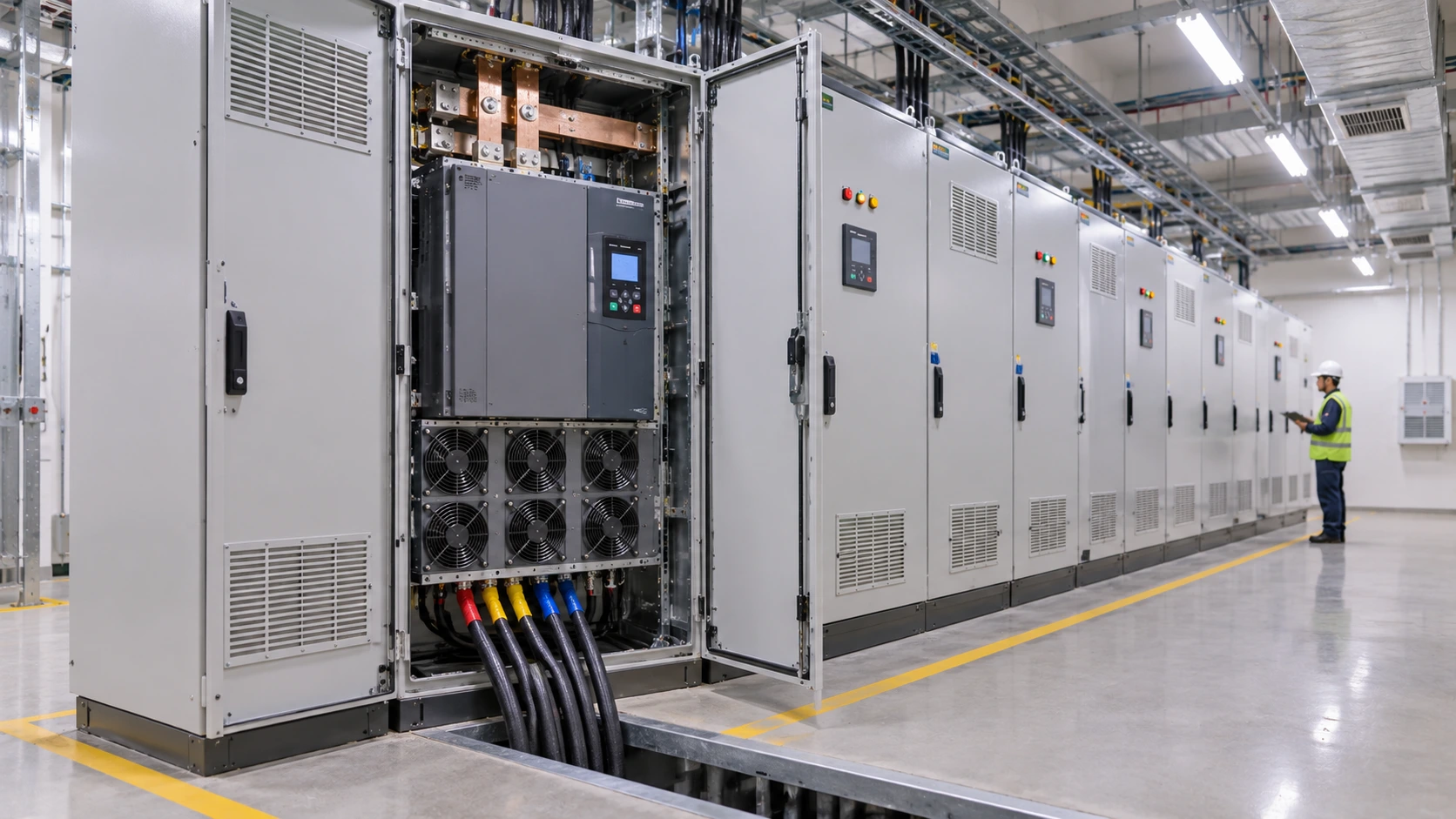
A high power drive can be bought as a bare module and assembled into a panel by a panel builder, or as an enclosed drive system that arrives complete. An enclosed drive system is a factory-built cabinet that contains the drive, input circuit breaker, line chokes, cooling, wiring and terminals, tested together before delivery. The Altivar Process ATV960 is of this type: the catalog entry describes a drive in an IP23 PanelSeT enclosure with its circuit breaker and line chokes fitted as standard.
The enclosed system has three advantages. The assembly is designed, thermally verified and tested as one product, so the engineer is not responsible for the airflow, busbar layout or clearance of the assembly. Commissioning is faster, because the wiring is done and the protection is coordinated. And the footprint and the documentation are fixed, which helps layout and approval. The ATV960 in the 500 kW class occupies roughly 800 mm by 600 mm in plan and 2150 mm in height.
A custom panel suits an awkward room, a specific mix of components or a local specification that no catalog unit meets. It needs a panel builder with experience at this current level, a thermal calculation, and a verified short-circuit rating under IEC 61439. For most standard duties the enclosed system is the lower-risk route.
Reading the Ratings: 500 kW Normal Duty and 400 kW Heavy Duty
The catalog entry for the ATV960C50Q4X1 reads 500 kW at normal duty and 400 kW at heavy duty on a 400 V supply. The two ratings describe the same hardware at different overload capability.
| Specification | ATV960C50Q4X1 value |
|---|---|
| Supply voltage | 400 V class |
| Power, normal duty | 500 kW |
| Power, heavy duty | 400 kW |
| Continuous output current, normal and heavy duty | 900 A and 730 A |
| Output frequency | 0.1 to 599 Hz |
| Enclosure | IP23, PanelSeT SFN, about 800 × 600 × 2150 mm |
| Communication | EtherNet/IP, Modbus TCP, Modbus serial |
| Safety | Safe Torque Off, SIL 3 |
| Options | Encoder interface modules (digital, analogue, resolver), bypass, braking resistor |
Normal duty is for variable torque loads such as centrifugal pumps and fans, where the torque falls as the speed falls and overload demand is low. Heavy duty is for constant torque loads such as conveyors, crushers and compressors, where the drive must supply high overload for starting and for shock loads, and the same hardware is rated for lower power in exchange. Choosing the wrong duty is a common mistake: a conveyor sized on the normal duty figure will trip on overload at start.
The sizing check starts with the motor current. For a three-phase motor at 400 V, the line current is the power divided by root three, the voltage, the efficiency and the power factor. A 500 kW motor at 96 percent efficiency and a power factor of 0.88 draws about 854 A, and a 450 kW motor draws about 769 A. Both fit inside the 900 A normal duty current, with a margin that allows for the real operating point, which is usually below nameplate. Size by current, and check the overload and ambient limits as well. Our post on sizing a VFD for a 75 kW pump walks through the same method at a smaller scale.
Heat and Cooling: The 10 Kilowatts You Have to Remove
At 98 percent efficiency, a 500 kW drive wastes about 10 kW as heat. That heat has to leave the cabinet and the room, or the drive derates and eventually trips on over-temperature. The arithmetic is simple. Removing 10 kW with air that is allowed to warm by 15 °C needs an airflow of 10,000 divided by the product of air density (1.2 kg/m³), specific heat (about 1005 J/kg·K) and the 15 K rise, which gives about 0.55 m³/s, or roughly 2000 m³/h, of clean air through each drive.
Room cooling is the other half. Several drives in one room add up, and the air conditioning must remove their combined heat plus that of the transformers and panels. In the Gulf, where outdoor air can exceed 45 °C, free ventilation is rarely enough and the drives are derated by the manufacturer's curve. In dusty plants such as cement and mining, an IP23 enclosure that draws room air needs a clean, filtered room, or a higher enclosure class and ducted cooling.
Filters clog and fans wear, so the maintenance plan includes filter changes, fan replacement at the manufacturer's interval and a thermal check of the busbar joints under load. A rising heatsink temperature trend shows a clogging filter long before the drive trips.
Harmonics at 500 kW: Six-Pulse Front Ends and the Options
A standard drive rectifies the incoming AC through a six-pulse diode bridge, which draws current in short pulses and injects harmonic currents, mainly the 5th, 7th, 11th and 13th, back into the supply. The ratio of harmonic current to fundamental current, the total harmonic current distortion or THDi, is substantial for a plain six-pulse front end. The ATV960 range uses this six-pulse diode front end with line chokes as standard, and Schneider quotes a THDi figure for the family that is typical of that design, so a project must check the harmonic limits before assuming the drive passes.
The limits come from the supply side. IEEE 519 sets harmonic current and voltage limits at the point of common coupling, and the limits depend on the ratio of the short-circuit current at that point to the load current. A 500 kW drive on a strong supply may pass without treatment, while the same drive on a weak supply, or one of several large drives on a shared transformer, may not. The harmonic study should include every non-linear load on the bus.
Several fixes exist. A larger line reactor or a DC choke reduces distortion modestly. A 12-pulse arrangement, with a phase-shifting transformer feeding two rectifiers, cancels the 5th and 7th. An active front end draws near-sinusoidal current, and Schneider's low-harmonic and regenerative families, such as the ATV980, are built that way. A separate active harmonic filter, such as the AccuSine unit in the same catalog, treats a whole bus. The guide to selecting a harmonic filter for a factory explains how to choose between them.
Motor Cables, Bearings and Output Filters
The drive's output is a stream of fast voltage pulses, and at this power the effects reach the motor. A long cable between drive and motor can reflect the pulses and raise the voltage at the motor terminals to nearly twice the DC bus voltage, which stresses the winding insulation. A dV/dt filter or a sine filter reduces the stress, and the manufacturer states the maximum unfiltered cable length for each drive and motor combination.
Bearing currents are the other effect. The fast switching induces common-mode voltages on the shaft, and the current finds its way through the bearings, where it etches the races. Large motors on drives often specify an insulated bearing at the non-drive end, a shaft grounding ring, or both, together with symmetrical shielded cable and a low-impedance bond at both ends. The motor maker should be told that the motor will run on a drive, and given the drive's switching frequency.
A current of 900 A needs several cables per phase, commonly four or six conductors in parallel, laid with equal lengths and symmetrical routing so they share the current evenly. The drive terminals must accept the number and size of lugs, and a termination drawing at the design stage prevents the commonest on-site surprise.
Pumps, Voltage Class and Other Points
A VFD for large pumps has a few extra rules, and any VFD for large pumps on a pump station needs them written into the specification. Keep a minimum speed that holds the pump above its minimum continuous flow and keeps the motor cooled by its shaft fan, since a self-cooled motor at 30 percent speed gets 30 percent of its cooling air. Set skip frequencies if the pump or its pipework has a resonance at a certain speed. Use a PID loop on pressure or flow with a sensible ramp, because a fast ramp on a long pipeline can create water hammer. And check that the drive's current limit and ramp times suit the pump's inertia.
Voltage class changes the arithmetic. A 400 V VFD for a 500 kW motor carries about 854 A, as calculated above. At 690 V the same motor draws about 495 A, which halves the cable cross-section and cuts losses, and it is why mining and heavy industry plants with a 690 V supply often choose that class for a 500 kW VFD. The motor, the cables and the transformer then have to be rated for 690 V, and the insulation stress on the motor is higher, so confirm the winding insulation system with the motor maker.
Bypass, Safety and Communications
A bypass lets the motor run directly from the supply if the drive fails. The ATV960 offers an optional integral full-voltage bypass starter. The convenience is real, since a failed drive on a critical pump need not stop the process, but the arithmetic needs checking. A 450 kW motor started across the line draws about six times its full-load current, roughly 4.6 kA, which the transformer, the upstream breaker and the voltage drop must tolerate. Many plants fit a soft starter in the bypass for that reason, as discussed in our comparison of VFD and soft starter duty.
Safe Torque Off at SIL 3 is part of the ATV960 specification. STO removes the drive's ability to produce torque through a dual-channel hardware path, so it can serve as the output stage of a safety function such as an emergency stop or a guard interlock, without an external contactor. Our article on safety interlock switches and standstill monitoring shows how an STO input fits into a complete guard-locking chain.
Communications follow the plant network. EtherNet/IP and Modbus TCP are built in, with Modbus serial, and the drive reports current, speed, temperature, energy and faults to a PLC or SCADA system. When it trips, the fault history is the first evidence, and our article on VFD overcurrent trips at startup explains how to read it.
At this size a drive is selected by current, cooled by airflow and judged by its harmonics. The kilowatt figure on the nameplate is only the start of the specification.
The Energy Case: Affinity Laws on a Large Pump or Fan
The strongest financial case for a high power VFD is a centrifugal load. The affinity laws say that flow is proportional to speed, head to the square of speed, and power to the cube of speed. Running at 80 percent speed delivers 80 percent of the flow for 0.8 cubed, or 51 percent, of the power. At 90 percent speed the power is 73 percent.
Consider a 450 kW fan that runs for 6000 hours a year at an average of 80 percent speed instead of full speed with a damper. The shaft power falls from 450 kW to about 230 kW, a saving of about 220 kW. Over 6000 hours that is roughly 1.3 million kWh a year, and at 0.10 per kWh it is about 130,000 a year before the drive's own losses of around 2 percent and ignoring the damper's partial savings. Those figures are illustrative, and the real number depends on the load profile and, for pumps, on the static head, which reduces the saving because the cube law applies only to friction head. Even at half that estimate the saving repays a drive of this size in a few years.
The same logic applies to every large pump and fan that throttles its output. The post on reducing motor energy consumption without cutting production covers how to find those loads, and the article on the power analyzer versus the power quality analyzer explains how to measure the before and after.
Real-World Scenario: Replacing Throttle Valves on Cooling Water Pumps
This is an illustrative case. A process plant runs three 450 kW cooling water pumps, two in duty and one standby. Each pump runs at constant speed, and a throttle valve on the discharge holds the flow, burning energy in the valve. The plant's cooling demand varies with the season and with production, averaging about 80 percent of design flow.
The plant installs two high power VFD systems on the duty pumps, with the standby on a bypass. The drives are enclosed systems in IP23 cabinets, placed in an air-conditioned electrical room whose cooling is checked for the extra 20 kW of drive heat. A harmonic study shows the two drives together pass the utility limit, and line chokes are enough. Motor cables are run as four parallel conductors per phase with a shielded layout, and the motors receive insulated non-drive-end bearings.
The throttle valves are opened fully and the drives control flow by speed. At the average flow, the pumps run near 85 percent speed, because the system has some static head, and the power falls by about 35 to 40 percent. The plant measures the saving with a calibrated analyzer before and after, and the result goes into the project record as the evidence for the next retrofit. The standby pump on bypass keeps the system resilient if a drive trips, with a soft starter in the bypass limiting the starting current.
Specifying a High Power VFD
A short list of questions covers the specification. State the motor power, voltage, current, speed and the load type, normal or heavy duty, with the overload needed. State the supply: voltage, short-circuit level, transformer size and harmonic limits. State the environment: ambient temperature, dust, humidity and altitude, which sets the enclosure class and the derating. State the cable arrangement, the motor-cable length and the bearing protection. Decide whether a bypass, a braking resistor, regeneration or encoder feedback is needed. Name the communication protocols and the safety functions, and ask for the manufacturer's heat loss and airflow figures for the room design.
The Schneider Altivar Process ATV960 500 kW drive system in the TCC catalog is a worked example of the enclosed type, and the ATV980 regenerative drive system at 160 kW covers loads that return energy to the supply, such as downhill conveyors. TCC supplies and commissions these systems through its variable frequency drives service and its VFD supply and commissioning team, including the harmonic study, the cable and cooling review, parameter setup, and the commissioning record.
Frequently Asked Questions
What is a high power VFD?
A high power VFD is a variable frequency drive for motors above roughly 250 kW at low voltage, up to about 1 MW where medium voltage drives take over. At this size the drive is usually an enclosed system with an input breaker, line chokes, cooling and communications, and it needs a heat, harmonic and cable review before it is installed.
What size VFD do I need for a 500 kW motor?
Size by current, not by kilowatts alone. A 500 kW motor at 400 V, 96 percent efficiency and 0.88 power factor draws about 854 A, so a drive rated at 900 A normal duty, such as the 500 kW ATV960C50Q4X1, is the right class for a pump or fan. A constant torque load such as a conveyor needs the heavy duty rating, which is 400 kW and 730 A for the same drive.
How much heat does a 500 kW VFD produce?
At about 98 percent efficiency, a 500 kW drive dissipates about 10 kW as heat. Removing that with a 15 °C air temperature rise needs roughly 2000 m³/h of clean air, and the room cooling must handle the combined heat of all drives. In hot climates the drive may need derating, and the manufacturer's curve for the intake temperature governs.
Do large VFDs cause harmonic problems?
A standard six-pulse drive injects harmonic currents into the supply, and at 500 kW the effect can exceed the limits set by IEEE 519 or the utility, especially on weak supplies. Line reactors, 12-pulse designs, active front ends or active harmonic filters reduce it. A harmonic study that includes all non-linear loads on the bus should be done before the drive is bought.
Related products
Components from our catalogue relevant to this article — request a quote for availability, lead time and pricing.
/ATV650C31N4F Schneider Electric.webp "Schneider Electric Schneider Electric Altivar Process ATV650 Variable Speed Drive, 315 kW | Floor-standing VFD, 315kW, 400-480V, IP54, with disconnect switch")
Schneider Electric Altivar Process ATV650 Variable Speed Drive, 315 kW
Floor-standing VFD, 315kW, 400-480V, IP54, with disconnect switch
/ATV660C35Q4X1 Schneider Electric.webp "Schneider Electric Schneider Electric Altivar Process ATV660 Compact Drive System, 355 kW | Enclosed compact drive system, 355/280kW, 400V, IP23")
Schneider Electric Altivar Process ATV660 Compact Drive System, 355 kW
Enclosed compact drive system, 355/280kW, 400V, IP23
/ATV660C45Q4X1 Schneider Electric.webp "Schneider Electric Schneider Electric Altivar Process ATV660 Compact Drive System, 450 kW | Enclosed compact drive system, 450/355kW, 400V, IP23")
Schneider Electric Altivar Process ATV660 Compact Drive System, 450 kW
Enclosed compact drive system, 450/355kW, 400V, IP23
/ATV960C50Q4X1 Schneider Electric.webp "Schneider Electric Schneider Electric Altivar Process ATV960 High Performance Drive System, 500 kW | Enclosed high-performance drive system, 500/400kW, 400V, IP23")
Schneider Electric Altivar Process ATV960 High Performance Drive System, 500 kW
Enclosed high-performance drive system, 500/400kW, 400V, IP23