
How to Size a VFD for a 75 kW Industrial Pump: A Complete Worked Calculation

Quick Answer
How to size a VFD for a 75 kW centrifugal pump starts with the motor's actual full load current, not its kW rating, then corrects for duty class, altitude, and ambient temperature before the frame size is final.
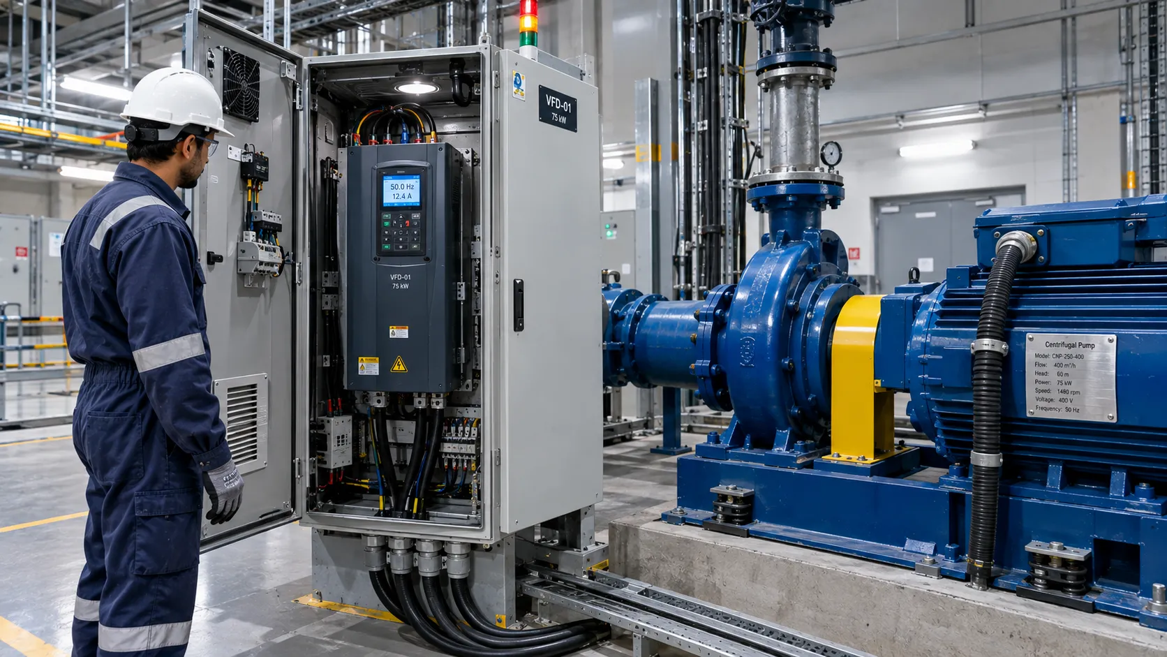
A 75 kW centrifugal pump motor draws roughly 131 A at 400 V on the nameplate, and that current figure, not the kilowatt number stamped next to it, is where sizing a VFD actually starts. Get the current wrong and every downstream decision is wrong with it: frame size, duty rating, cable gland, enclosure cooling. This is a complete variable frequency drive sizing guide and pump motor VFD selection guide built around one specific pump, worked front to back with real numbers, so you can see exactly how to size a VFD for a load like this rather than pulling a frame size off a vendor chart and hoping it holds up in a hot electrical room at altitude.
If the application already needs continuous speed control rather than a simple controlled start, the VFD vs soft starter decision is already settled, and drive sizing for centrifugal pump duty is what's left to solve. The job sounds simple: match a drive to a motor. In practice it's several corrections stacked on one base number, and skipping any of them is how drives end up running hot, tripping under load, or failing an acceptance test that should have been a formality. What follows covers the motor's full load current, the variable torque VFD sizing question (variable torque versus constant torque) that decides whether a heavy duty or normal duty rated drive is correct, the overload rating that protects the motor during upset conditions, and the altitude and temperature derating most sizing charts skip.
Start From the Motor's Actual Full-Load Current, Not the Kilowatt Rating
Every VFD sizing calculation has to begin with the motor nameplate, not the pump's duty point and not the kW rating alone. A kilowatt figure tells you power; it does not tell you current, and the motor full load current VFD sizing depends on is what the drive's output stage, the cabling, and the thermal protection are actually rated against. This is the first and most skipped step in how to select a VFD for a motor: size the VFD for the motor current first, then layer everything else on top.
For a 4-pole, 400 V, IE3 induction motor of this size (1500 rpm synchronous at 50 Hz, the standard speed for a medium-size centrifugal pump), catalog data from multiple manufacturers converges tightly around 129 to 131 A at 400 V, with a power factor near 0.87 and full-load efficiency near 95%, consistent with the minimum efficiency IEC 60034-30-1 sets for an IE3 motor in this power band. You can derive the same number from the standard three-phase current formula:
I = P / (√3 × V × PF × η)
Plugging in 75,000 W, 400 V, a power factor of 0.87, and an efficiency of 0.95 gives I = 75,000 / (1.732 × 400 × 0.87 × 0.95) ≈ 131 A, a 75 kW motor amps figure that matches published IE3 catalog values. That's the VFD sizing formula in full, not the simplified VFD kW to amps shortcut on a lot of generic charts. A quick VFD amperage calculator or a "divide by voltage" approximation lands in the right neighborhood but quietly assumes a power factor and efficiency that may not match your actual motor. The nameplate on the motor you're actually buying, not a generic 75kW motor VFD reference table, is the only number that should drive the final VFD current rating calculation.
These numbers travel differently across markets, and the US is one place where practice genuinely diverges. In the Gulf, the UK, South Africa, and Russia, 400 V IEC-based motors and the full load current conventions above are standard. In the United States, a 75 kW motor is more commonly specified as its nearest NEMA horsepower equivalent, roughly 100 hp (75 kW × 1.341 = 100.6 hp), at 460 V. NEC Table 430.250 lists the full load current for a 100 hp, 460 V three-phase motor at 124 A, used for conductor and short-circuit protection sizing, not the motor's own nameplate current for overload settings. The two figures aren't interchangeable, but they make the same point: current scales with voltage, and any VFD kW to amps conversion has to specify the voltage class first.
Variable Torque vs Constant Torque: Why a Centrifugal Pump Changes the Answer
This is the step most VFD sizing chart shortcuts skip, and it's the one that actually determines whether you need a heavy duty or normal duty rated drive. It's also the real core of how to size a VFD correctly rather than approximately: respecting what the load's physics demands, not just what its nameplate says.
A centrifugal pump is a variable torque load. Its torque requirement rises with the square of speed and its power requirement rises with the cube of speed, the same affinity laws that make VFD-driven flow control such a strong energy case for pumps and fans. At low speed, a centrifugal pump demands comparatively little torque, and never needs the sustained high-torque overload that a constant torque load (a screw compressor, an extruder, a conveyor under a loaded hopper) needs just to get started. How the drive regulates that torque internally, through open-loop or closed-loop vector control, is a separate design question from the duty rating, but the two interact: true vector control holds torque accuracy at the low speeds a throttled pump needs.
This is exactly why VFD sizing for centrifugal pump loads diverges from constant torque sizing, even with identical nameplate kW. A normal duty (ND) rating is built around variable torque loads, with lower overload headroom, since the load rarely demands sustained overload. A heavy duty (HD) rating is built around constant torque loads, with higher headroom, because starting a loaded conveyor or compressor genuinely requires it.
For centrifugal pump VFD selection, normal duty is almost always correct, not heavy duty. Specifying heavy duty on a pump isn't wrong in the sense that it will fail. It's wrong in the sense that it's oversized for the duty being asked of it. Oversizing a drive by a frame size or two to cover torque that will never materialize is money and panel space spent on a problem that doesn't exist, the whole point of doing pump VFD sizing properly: match duty rating to load physics, not a reflexive preference for the "stronger-sounding" option.
Heavy Duty vs Normal Duty VFD: Why the Distinction Decides the Frame Size
The heavy duty vs normal duty VFD distinction isn't marketing language. It's a published overload rating most low-voltage drives carry as a dual specification, letting the same physical drive be configured either way through a parameter setting.
Normal duty typically allows 110% of rated current for 60 seconds, available once every 10 minutes. Heavy duty typically allows 150% for the same 60 seconds on the same cadence. Because continuous current rating and overload headroom trade off against the same silicon, the same frame carries a lower continuous current number under heavy duty than under normal duty, commonly described as stepping down roughly one frame size in continuous rating.
| Characteristic | Normal Duty (ND) | Heavy Duty (HD) |
|---|---|---|
| Typical overload | 110% of rated current | 150% of rated current |
| Overload duration | 60 seconds | 60 seconds |
| Typical overload cadence | Once per 10 minutes | Once per 10 minutes |
| Torque behavior assumed | Variable torque (torque ∝ speed²) | Constant torque (torque independent of speed) |
| Typical loads | Centrifugal pumps, fans, blowers | Compressors, conveyors, extruders, mixers |
| Continuous current for a given frame | Higher | Lower (same frame, different rating) |
| Best fit for this 75 kW pump | Yes | Oversized for the duty |
Reading a VFD sizing chart without checking which duty rating the listed amperage applies to is a common, avoidable error. A chart's "75 kW" row might reference the heavy duty rating of a physically larger frame, the normal duty rating of a smaller one, or occasionally both side by side. A VFD motor hp chart that doesn't specify duty class alongside the amperage isn't incomplete by accident; duty class is a drive-specific parameter, not a universal constant, and no chart substitutes for the actual datasheet for the frame being specified. The same discipline applies one level up at the panel, where our medium voltage motor VFD panel selection checklist covers how enclosure heat from several drives at once compounds everything below.
A VFD sized only from the motor's kW rating, without checking duty class, altitude, and ambient temperature, is sized to the nameplate. It is not sized to the installation.
VFD Overload Rating in Practice: What 110% and 150% Actually Protect Against
The VFD overload rating matters for a reason that has nothing to do with marketing headroom: it's what gets the pump through a transient without tripping, and what the drive's internal thermal model uses to decide whether a current spike is normal operation or a fault worth protecting against. This overload headroom against real transients is the part of how to size a VFD that a kW-only comparison never touches.
For a centrifugal pump, the overload events that matter are mostly process-driven, not mechanical: a partially closed downstream valve during startup, a momentary surge from an upstream level controller feeding a 4-20 mA loop, a brief run against higher static head while a parallel pump comes online. These create short excursions above steady-state, not sustained ones, and a drive integrated into that kind of closed-loop instrumentation and control scheme needs headroom matching the actual disturbance. A 110% for 60 seconds normal duty rating covers that profile comfortably; it would not cover a positive displacement pump starting against a closed valve, exactly the profile heavy duty ratings exist for.
This is also where undersizing shows up fastest. A drive matched to the motor's exact continuous current with nothing left over will trip on its first legitimate process transient. The fix isn't a heavy duty frame; it's confirming the normal duty rating of the selected frame clears the motor's full load current with the overload window intact, a different check than matching kW ratings on the nameplate.
VFD Derating Altitude and Temperature: What Changes Above 1,000 Meters and 40°C
This is the step that generic VFD amperage calculators and online VFD sizing chart tools almost never include, and it's the step that causes the most real-world nuisance trips on drives that were sized correctly on paper.
Altitude. A VFD's output semiconductors are cooled by moving air across a heatsink, and air density falls as altitude increases, so the drive's safe continuous current rating falls with it. Across major low-voltage drive platforms, the published derating convention is consistent, and Danfoss states it in its technical guidance: no derating up to 1,000 meters above sea level, and above that, continuous output current derates by approximately 1% for every 100 meters, typically up to a maximum rated altitude of 2,000 to 4,000 meters. Treat that as the VFD derating altitude starting number, then confirm against the specific drive's hardware manual, since the ceiling and slope are manufacturer-specific.
For a site at 1,700 meters, common across South Africa's Highveld industrial belt, that works out to (1,700 − 1,000) / 100 × 1% = 7% derating off the drive's sea-level continuous current rating.
Ambient temperature. Separately from altitude, every VFD has a rated ambient temperature, commonly 40°C, above which continuous output current must also be derated, because the drive's internal components hit their thermal limits regardless of air density. Published rates vary by manufacturer, roughly 1% per degree C between 40°C and 50°C on some platforms, 2% to 3% per degree C on others. Treat 1% to 2.5% per degree C above rated ambient as a reasonable VFD derating temperature planning range, then verify the exact curve for the frame being specified, since this figure differs enough between brands to change a sizing decision on its own.
For an electrical room in the Gulf running at a 50°C design ambient, realistic for a non-air-conditioned enclosure in the UAE, Saudi Arabia, or Qatar, that's (50 − 40) × 1% = 10% derating at the low end of the typical range, more on platforms with a steeper curve.
These two corrections stack multiplicatively, not by simple addition, since they're independent effects on the same cooling system. A drive facing both a 7% altitude derating and a 10% temperature derating isn't looking at a combined 17% reduction; it's facing roughly 1 − (0.93 × 0.90) = 16.3%. Treating them as additive on a severe site will understate the real derating.
A Real-World Scenario: The Highveld Dewatering Pump That Tripped on Day One
A platinum mine on South Africa's Highveld, sitting at roughly 1,700 meters, commissioned a new dewatering station built around three 75 kW centrifugal pumps, each specified with what looked on paper like an adequately sized drive: a normal duty frame with a sea-level rating comfortably above the motor's 131 A full load current.
The problem showed up within the first week, not during commissioning. Tests ran the pumps at partial load on a cool morning, and everything passed. Once the station went into full production, running two of the three pumps continuously against a higher static head during summer, drive number two began tripping on an internal overtemperature fault, intermittently at first, then reliably within an hour of steady-state operation.
The root cause traced back to exactly the correction the original calculation had skipped: altitude. The drive's nameplate rating had been compared directly against the 131 A motor current with only a small margin, which looked sufficient at sea level. At 1,700 meters, with the roughly 7% altitude derating applied, the drive's actual safe output fell below what the pump demanded at its real operating point, not the lighter partial-load condition commissioning had tested. The fix required stepping up to the next frame size, a mid-project change that cost far more in schedule and lead time than getting the VFD sizing calculation right the first time would have.
Commissioning at partial load on a mild day tells you almost nothing about whether a VFD will survive full load on the hottest day the site actually sees.
Cable Length, Output Filters, and the Insulation Question
Sizing the drive's current rating correctly doesn't finish the job if the cable run between drive and motor is long enough to create its own problem. VFDs switch output voltage at high frequency, and that waveform reflects at the impedance mismatch between cable and motor windings, producing voltage spikes at the motor terminals that can significantly exceed the drive's DC bus voltage on long runs; this is generally called reflected wave.
At 400 V, this stress is real but manageable. IEC TS 60034-25, the specification covering AC machines designed for converter supply, treats standard low-voltage motors below roughly 500 V as generally tolerant of converter switching without a reinforced winding insulation system, provided cable length stays within reasonable limits. Beyond those limits, typically around 50 meters without mitigation and extendable to 100 meters or more with an output choke depending on switching frequency, a dV/dt filter or output reactor becomes the correct response rather than an optional extra. In the US market, NEMA MG 1 Part 31 sets a parallel requirement for inverter-fed motors rated 600 V or less: winding insulation must withstand peak voltage up to 3.1 times rated line-to-line voltage. This is worth knowing when a US-sourced motor is paired with an IEC-sourced drive.
For a pump station where the drive sits some distance from the pump house, confirming actual cable length against the manufacturer's unfiltered-length table belongs in the same sizing exercise as the current and derating calculations, not a separate conversation after the cable is pulled. Confirm it during the same pass as the VFD commissioning sequence, since insulation and continuity checks at startup are where a marginal cable run first shows up.
Putting the Full VFD Sizing Calculation Together
Here's how to size a VFD for this pump end to end, the complete VFD capacity calculation with every correction applied in sequence:
Start with the motor nameplate full load current: 131 A at 400 V for this 75 kW, 4-pole motor. Confirm the load is variable torque, true for a centrifugal pump, and select a normal duty rated drive rather than heavy duty, since the application will never demand the sustained 150% overload heavy duty provides. Select a frame whose ND continuous current clears 131 A with the standard overload window intact, not a frame sized to 131 A with nothing left over. Apply site corrections next: roughly 1% per 100 meters above 1,000 meters altitude, and the VFD derating temperature correction above rated ambient, multiplied rather than added when both apply. Compare the resulting number back against 131 A; if the frame doesn't clear it, step up and repeat the check, rather than splitting the difference and hoping the margin holds in August.
This same VFD sizing for pump logic applies whether you're specifying one unit or a whole pump station, and it's worth re-running at detailed design, not just budget stage, since the vendor quote that arrives weeks later often reflects a different frame, firmware, or duty configuration than the budget number assumed. Treat any VFD kW to amps shortcut on a vendor chart as a starting estimate, then confirm it against the nameplate math above.
Getting VFD sizing for pump duty right on one pump is a manageable calculation. Getting it right across a pump station or a process unit with dozens of variable-torque and constant-torque loads at different altitudes and ambient conditions is where knowing how to size a VFD on paper is no longer enough on its own. Techno Control Corporation's variable frequency drives team handles this specification work end to end, from the current and duty-rating calculation through altitude and temperature correction to final frame selection, sources the hardware through authorized VFD supply channels, and audits an existing drive fleet through power system optimization work when a plant suspects part of its installed base was never corrected for site conditions.
Frequently Asked Questions
How do I size a VFD for a 75 kW industrial pump?
For VFD selection for pump application work, start from the motor nameplate full load current, roughly 131 A for a 400 V, 4-pole, IE3 motor of this size, not the kW rating alone. Confirm the pump is a variable torque load and select a normal duty rated drive whose continuous current clears the motor's full load current with the standard overload window intact, then apply altitude and ambient temperature derating for the actual installation site before confirming the final frame size.
What is the difference between heavy duty and normal duty VFD ratings?
Normal duty typically allows 110% overload for 60 seconds and is built for variable torque loads like centrifugal pumps and fans, where torque requirements rise with the square of speed. Heavy duty typically allows 150% overload for 60 seconds and is built for constant torque loads like compressors and conveyors that need sustained high torque to start under load. The same physical drive frame usually carries a higher continuous current rating under normal duty than under heavy duty configuration.
How does altitude affect VFD derating?
VFDs cool their output semiconductors with moving air, and thinner air at altitude carries away less heat, so continuous output current must be derated above a threshold altitude, commonly 1,000 meters, at a rate of roughly 1% per additional 100 meters, a convention published across major drive platforms. A site at 1,700 meters, typical of South Africa's Highveld, needs roughly 7% derating off the drive's sea-level continuous rating before comparing it against the motor's full load current.
How do I convert VFD kW rating to amps?
Use the three-phase current formula, current equals power divided by the square root of 3 times voltage times power factor times efficiency, with the motor's actual nameplate power factor and efficiency rather than assumed values. For the 75 kW, 400 V motor in this guide, that calculation returns approximately 131 A, matching published catalog full load current values for IE3 motors of this size and pole count.
Related products
Components from our catalogue relevant to this article — request a quote for availability, lead time and pricing.
/Innomotics GP 1LE1003 160.0kW 4P.webp "Innomotics 1LE1003 Innomotics - SIMOTICS GP IE3 Low-Voltage Motor, 160 kW 4-Pole | Aluminum IE3 low-voltage motor, 4-pole 1500 rpm sync, 160 kW build")
1LE1003 Innomotics - SIMOTICS GP IE3 Low-Voltage Motor, 160 kW 4-Pole
Aluminum IE3 low-voltage motor, 4-pole 1500 rpm sync, 160 kW build
/SD Motor 1LE1583-1AA4 - 3.0 kW Frame 100 L.webp "Innomotics 1LE1583-1AA4 Innomotics - SIMOTICS SD IE3 Cast-Iron Motor, 3 kW | Cast-iron IE3 motor, 2-pole, 3 kW, Frame 100 L")
1LE1583-1AA4 Innomotics - SIMOTICS SD IE3 Cast-Iron Motor, 3 kW
Cast-iron IE3 motor, 2-pole, 3 kW, Frame 100 L
/TC625 AF100 ABB - Coaxial Modem 3BSE002224R1.png "ABB TC625 AF100 ABB - Coaxial Modem 3BSE002224R1 | Coaxial modem TC625 AF100")
TC625 AF100 ABB - Coaxial Modem 3BSE002224R1
Coaxial modem TC625 AF100
/SB512 ABB - Power Supply 3BSE002098R1.png "ABB SB512 ABB - Power Supply 3BSE002098R1 | SB512 power supply module")
SB512 ABB - Power Supply 3BSE002098R1
SB512 power supply module