
Power Analyzer vs Power Quality Analyzer: Which One Your Test Job Needs

Quick Answer
A power analyzer measures power and efficiency with laboratory accuracy, and a power quality analyzer records events on a live network. This guide shows which one a test job needs and where the Fluke Norma 4000 fits.
Two engineers clamp instruments onto the same variable frequency drive and get different efficiency figures. One reports 96.2 percent, the other 94.8. Both instruments are calibrated, both engineers wired them correctly by their own account, and the supplier's guarantee reads 95.5. Whether the drive passes depends entirely on whose number is believed, and the argument that follows can hold up a contract payment for weeks. The cause is usually not carelessness. It is that the two instruments were built to answer different questions.
A power analyzer is a precision instrument that measures voltage, current, power, harmonics and efficiency with accuracy in the hundredths of a percent, usually on a bench or a test stand, and often on distorted waveforms from drives and inverters. A power quality analyzer is a monitoring instrument that records what happens on a live electrical network over days or weeks, including sags, swells, transients, flicker and harmonics, to a standard that makes the data defensible with a utility. This guide explains how a three phase power analyzer works, how the two instruments differ, why accuracy decides VFD efficiency measurement and motor efficiency testing, and how to choose, with the Fluke Norma 4000 as the reference precision unit.
Two Instruments, Two Questions
The word analyzer hides the difference. A power quality analyzer answers the question of what the network is doing: how often the voltage dips, how much distortion the plant puts back on the supply, whether the supply meets the utility standard, and when an event occurred. It is a recorder, left connected for a week and read afterwards.
A power analyzer answers a different question: how much power went in, how much came out, and what was lost in between. It is a measuring instrument for engineering decisions about equipment, such as the efficiency of a drive, a motor, a transformer or a UPS, and it is judged on how closely its numbers match the true value, on any waveform, at any frequency. It is typically used for minutes or hours on a defined test, not for weeks.
A third device sits between them. A three-phase energy logger, such as the Fluke 1734 in the TCC catalog, records power and energy over days at moderate accuracy for energy surveys. It suits an energy audit, and it does not replace either of the other two. The mistake that causes the argument above is using a survey-grade or monitoring instrument on a question that needs precision.
What a Power Analyzer Measures and How
A modern three phase power analyzer samples the voltage and current waveforms at a very high rate, several times the highest frequency of interest, and calculates everything from the samples. It does not assume a sine wave, so it handles the pulse-width-modulated waveforms that a drive puts out as accurately as a clean 50 Hz supply. It reports active power in watts, apparent power, reactive power, power factor, true RMS voltage and current, the harmonic spectrum, and, when torque and speed signals are connected, mechanical power and efficiency.
Bandwidth and sampling are the headline specifications. The Fluke Norma 4000 with its PP42 power module is listed at a basic accuracy of 0.2 percent, a bandwidth from DC to 3 MHz, and a sampling rate in the hundreds of kilohertz, which is far above the switching frequency of any drive. It displays harmonics up to the 40th order, FFT spectrum, oscilloscope and vector views, and has isolated inputs to 1000 V. The accuracy statement in a data sheet is written in two parts, a share of the reading plus a share of the range, so it pays to read both.
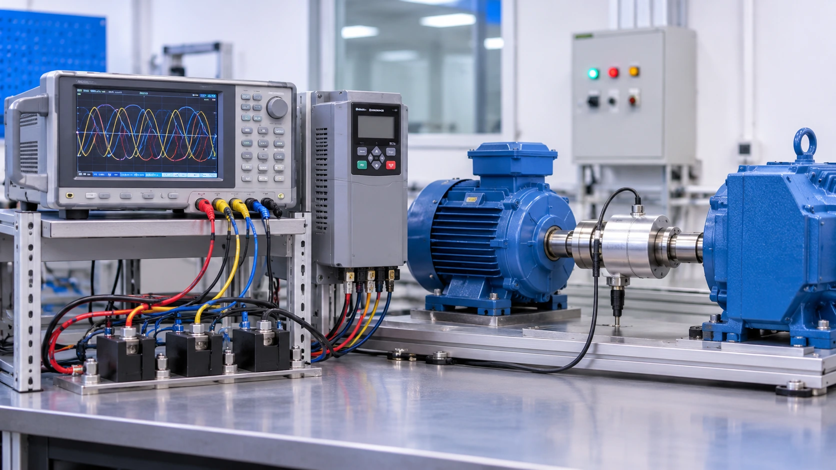
A precision power analyzer also handles synchronous measurement of several channels. Input power, output power and mechanical power are measured at the same instants, so the efficiency calculated from them is not distorted by timing differences. That is how Fluke describes the Norma family's use on drives: dynamic torque calculation and detailed spectrum analysis allow the switching losses of the inverter to be measured, and synchronous electrical input and mechanical output measurements give the losses of each component and of the whole drive system.
What a Power Quality Analyzer Measures
A power quality analyzer records the supply voltage and load current continuously and detects events. It logs the voltage magnitude and frequency, flags dips and swells with their depth and duration, captures transients, measures flicker, tracks harmonic distortion and unbalance, and timestamps everything. It is designed around standards: IEC 61000-4-30 defines how each parameter is to be measured and how accurately, and a Class A instrument meets the strictest set of requirements, which is why its data is accepted in disputes with a utility. EN 50160 sets the voltage characteristics that the supply is expected to meet, and IEEE 519 sets harmonic limits at the point of common coupling.
The strengths of the instrument are the duration and the event handling. It can sit on a feeder for a month and show that a production stoppage at 02:10 coincided with a voltage sag lasting 80 milliseconds. Its accuracy is aimed at compliance, usually a few tenths of a percent on voltage, and its bandwidth is set by the standard, a few kilohertz for harmonic work, with some models extending to the supraharmonic range up to 150 kHz. It does not need the extreme accuracy of a lab instrument, and it does not usually measure torque or compute efficiency.
Two of our earlier articles explain the situations where a power quality analyzer earns its keep. The guide to selecting a harmonic filter starts with a harmonic survey, and the post on reducing motor energy consumption relies on logged load profiles. Both use monitoring-grade data, and neither needs a precision analyzer.
Power Analyzer vs Power Quality Analyzer: Side by Side
The comparison of a power analyzer vs power quality analyzer comes down to the question each answers, the accuracy each needs, and how long each stays connected.
| Feature | Power analyzer | Power quality analyzer | Energy logger |
|---|---|---|---|
| Main question | How much power, how much loss, what efficiency | Is the network healthy, what events occurred | How much energy over time |
| Typical accuracy | About 0.01 to 0.2 percent on power | About 0.1 to 0.5 percent on voltage | About 0.5 to 1 percent |
| Bandwidth | DC to hundreds of kHz or MHz | Standard-defined, kHz range | Fundamental and low harmonics |
| Governing basis | Manufacturer accuracy and calibration | IEC 61000-4-30 Class A or S | Manufacturer |
| Duration of use | Minutes to hours on a test | Days to weeks on a network | Days to weeks |
| Torque and speed inputs | Yes, for mechanical power | Usually no | No |
| Typical user | Lab, R&D, factory acceptance, drive makers | Utilities, consultants, plant engineers | Energy auditors |
| Relative cost | Highest | Medium | Lowest |
If a number will be used to decide a contract, a power analyzer is the instrument. If a number will be used to find an event or prove compliance, a power quality analyzer is. If it will be used to size a saving, a logger is enough.
Why Accuracy Decides VFD Efficiency Measurement
Efficiency is a ratio of two powers, and each carries its own error. VFD efficiency measurement compares the power leaving the drive with the power entering it, or compares the shaft power of the motor with the electrical power into the drive for the whole drive system. The differences being measured are small. A high-efficiency drive loses two to four percent of its input as heat, and the gap between a good drive and a very good one can be half a percentage point.
Take a worked example, with illustrative numbers. A drive and motor take 80.0 kW at the drive input and deliver 73.9 kW at the motor shaft, so the system efficiency is 73.9 divided by 80.0, or 92.4 percent. Now consider the error budget. If both the input power and the output power are measured with an instrument of 0.2 percent accuracy, the combined uncertainty is about the square root of the sum of the squares, 0.28 percent, which gives roughly ±0.26 percentage points on 92.4 percent. The true efficiency lies between 92.1 and 92.7 percent. With a mechanical measurement, the torque transducer adds its own error, commonly 0.1 to 0.2 percent, and the budget grows slightly.
Now repeat the calculation with a general-purpose instrument of 1 percent accuracy on each channel. The combined uncertainty is 1.4 percent, or ±1.3 percentage points. The same drive could read 91.1 or 93.7 percent, a spread wider than the gap between efficiency classes. That is how two engineers with two calibrated instruments produce 96.2 and 94.8 on the same drive.
The waveform adds its own error. The drive's output is a pulse-width-modulated waveform with a carrier frequency of several kilohertz, and the harmonics near and above the carrier carry real power and cause real heating in the motor. A meter with a bandwidth of a few kilohertz misses them, and a meter that assumes a sinusoidal waveform miscalculates the power. A precision power analyzer with a bandwidth in the megahertz and a sampling rate in the hundreds of kilohertz captures the whole spectrum and calculates power from the samples, which is why it is the instrument named in efficiency test standards. The standard IEC 61800-9-2 defines energy efficiency classes for drive systems and the loss measurement approach, and the test points follow it.
Motor Efficiency Testing: Input-Output and Standards
Motor efficiency testing follows IEC 60034-2-1, which sets out the methods for determining the efficiency of rotating electrical machines. The direct method, called input-output, measures the electrical input power to the motor and the mechanical output power from torque and speed, and divides one by the other. The result is only as good as the weakest of the three measurements: electrical power, torque and speed. Speed is easy to measure to a very small error. Torque is the hard one. Electrical power is where a power analyzer earns its fee.
Indirect methods avoid measuring torque by measuring losses separately: no-load losses, load-dependent losses, friction and windage, and stray load losses, which are estimated or measured by a defined procedure. For larger motors, indirect methods are common because a torque transducer for a large machine is expensive and a dynamometer is heavy. Converter-fed motors add the harmonic losses from the drive's waveform, and a companion part of the IEC 60034 series covers them. The efficiency classes IE1 to IE4 in IEC 60034-30-1 use the test results to rank motors.
For a plant, the uses are two. The first is verification: a purchaser checks that a new motor or drive meets its claimed efficiency, particularly where a contract carries a penalty. Our guide to how to compare motor quotations explains how efficiency figures enter the commercial comparison. The second is characterization, where an engineer measures the losses of a motor and drive across a range of speeds and loads to find the best operating point, which feeds directly into the energy-saving work in our article on sizing a VFD for a 75 kW pump.
Wiring, Sensors and Setup Mistakes
Most disputed readings come from setup, not from the instrument. The wiring scheme must match the system: a three-wire system uses a two-wattmeter connection, a four-wire system with a neutral uses three, and a wrong scheme produces power errors that no calibration cures. Voltage leads should be short and routed away from power cables. Current is measured either directly, through the analyzer's own current input, or through an external sensor. The PP42 module takes up to 20 A directly, so larger drives need a current transformer, a Rogowski coil or a precision shunt, and the sensor's own accuracy and phase error then dominate the budget. A transformer with a phase error of a quarter of a degree produces a visible error in power at low power factor, because the active power depends on the cosine of the angle between voltage and current, and at a power factor of 0.1 a small angle error becomes a large share of the reading. The same effect makes transformer loss measurement, where the power factor is very low, one of the most demanding jobs for a precision instrument.
Timing and conditions matter as well. Efficiency should be measured after the motor and drive have reached thermal equilibrium, because winding resistance and losses change as they heat. Measurements at each load point should be averaged over a defined period, long enough to smooth load ripple. The torque transducer needs zeroing, and its speed and torque signals must enter the analyzer on the correct channels, scaled correctly. And all instruments need current calibration certificates, because a precision analyzer that is two years out of calibration offers no more than a general-purpose meter.
Calibration status and the instrument's warm-up time deserve a line in the test procedure too. A final mistake is to use a clamp meter for a drive output. A basic true-RMS clamp meter has a bandwidth of a few kilohertz and will read a drive's output current with an error that depends on the carrier frequency. Use it for fault finding and load checks, and not for efficiency claims.
The Fluke Norma 4000 and the Instruments Around It
The Fluke Norma 4000 in the TCC catalog is a three-phase precision power analyzer built from PP42 power modules, with 0.2 percent basic accuracy, a bandwidth from DC to 3 MHz, a 20 A direct current range, harmonics to the 40th order, FFT, scope and vector modes, and isolated inputs to 1000 V. NormaView software handles configuration, logging and reporting. It is used in development laboratories, in factory acceptance tests of drives and motors, and wherever a contract rests on a loss or efficiency figure.
The Fluke Norma 4000 power analyzer is one end of a range. For energy surveys, the Fluke 1734 three-phase energy logger records for days at moderate accuracy. For fault finding, the Fluke 376 FC clamp meter reads current and voltage quickly. And for long-term network monitoring to IEC 61000-4-30, a Class A power quality analyzer is the correct tool. Matching the instrument to the decision is more important than buying the most expensive one, and TCC's range covers the whole ladder.
Real-World Scenario: A Loss Guarantee at Factory Acceptance
This case is an illustration. A plant orders a 75 kW drive and motor package with a contractual guarantee: system efficiency of at least 95.5 percent at rated load, with a payment penalty for each tenth of a percent below. At the factory acceptance test, the supplier measures 95.7 percent using its laboratory analyzer, with a stated uncertainty of ±0.3 percentage points. The plant's engineer, using a power quality analyzer with 0.5 percent accuracy, measures 95.1 percent and claims a failure.
The two numbers are not in conflict, because the second instrument's uncertainty is about ±0.9 points. The right resolution is not to argue about one reading against the other, but to agree the instrument and its uncertainty before the test. The parties repeat the test with a calibrated precision power analyzer, a torque transducer with a current certificate, a defined warm-up period, and averaged readings. The measured efficiency is 95.6 percent, inside the uncertainty of the guarantee, and the contract defines how uncertainty is treated, so the package is accepted.
The lesson for the buyer is simple. Put the test method, the instrument class, the uncertainty treatment and the load points into the purchase order. A guarantee without a measurement method invites exactly this dispute.
Choosing: Three Questions
Three questions decide the instrument. What decision will the number support? A contract, a design, or a compliance record points to a precision power analyzer or a Class A quality analyzer, and a savings estimate can use a logger. How small is the difference that must be resolved? If it is under a percentage point, only a precision instrument will resolve it. And how long must the measurement run? Minutes on a test stand call for a power analyzer, and weeks on a live feeder call for a quality analyzer.
TCC's instrumentation and control team supplies and calibrates precision test equipment, and its audit and power system optimization service uses the right instrument for each measurement in an energy or power quality study. For drives above a few hundred kilowatts, where a loss guarantee carries real money, the article on high power VFD systems covers what to ask the supplier for, and the guide to motor testing methods covers the diagnostic tests that complement an efficiency measurement.
Frequently Asked Questions
What is the difference between a power analyzer and a power quality analyzer?
A power analyzer is a precision instrument for measuring power, losses and efficiency, with accuracy of hundredths of a percent and wide bandwidth, usually on a test stand. A power quality analyzer is a monitoring instrument that logs events such as sags, swells, flicker and harmonics on a live network, built to IEC 61000-4-30. Use the first for equipment decisions and the second for network health and compliance.
Why does VFD efficiency measurement need a precision power analyzer?
Efficiency is the ratio of two powers, and the differences between good drives are small, often under a percentage point. A general-purpose instrument with 1 percent accuracy per channel gives an uncertainty of more than a point on efficiency, and its limited bandwidth misses the drive's switching harmonics. A precision analyzer with 0.2 percent accuracy and megahertz bandwidth keeps the uncertainty below about 0.3 points.
Which standard governs motor efficiency testing?
IEC 60034-2-1 defines the methods for determining the efficiency of rotating electrical machines, including the direct input-output method and the indirect loss-summation methods. IEC 60034-30-1 defines the efficiency classes IE1 to IE4, and IEC 61800-9-2 covers the energy efficiency of drive systems. Test reports should state which method and which standard edition were used.
Can I use a clamp meter to measure drive efficiency?
No. A standard clamp meter has limited bandwidth and assumes a near-sinusoidal waveform, so it misreads the pulse-width-modulated output of a drive, and its accuracy is too coarse for efficiency work. Use it for load checks and fault finding. For efficiency, use a three phase power analyzer with adequate bandwidth, correct wiring and calibrated current sensors.
Related products
Components from our catalogue relevant to this article — request a quote for availability, lead time and pricing.
/3110978 Fluke - N4K 3PP42IPB.webp "Fluke Fluke Norma 4000 High Precision Power Analyzer, 3-Phase | High precision power analyzer, 3 phases with PP42 modules, 0.2% accuracy, 3 MHz")
Fluke Norma 4000 High Precision Power Analyzer, 3-Phase
High precision power analyzer, 3 phases with PP42 modules, 0.2% accuracy, 3 MHz
/1734 B Fluke.webp "Fluke Fluke 1734 Three-Phase Electrical Energy Logger | Three-phase energy logger, 600 V CAT IV / 1000 V CAT III, 3 flexible probes, Fluke Connect")
Fluke 1734 Three-Phase Electrical Energy Logger
Three-phase energy logger, 600 V CAT IV / 1000 V CAT III, 3 flexible probes, Fluke Connect
/2096379 - Fluke L210.webp "Fluke Fluke L210 Probe Light Kit | Test probe LED light with 8 in probe extenders")
Fluke L210 Probe Light Kit
Test probe LED light with 8 in probe extenders
/2679831 Fluke - 922 KIT.webp "Fluke Fluke 922 Kit Airflow Meter / Micromanometer with Pitot Tube | Airflow meter: pressure +/-4000 Pa, velocity 1-80 m/s, flow; kit with 12 in pitot tube")
Fluke 922 Kit Airflow Meter / Micromanometer with Pitot Tube
Airflow meter: pressure +/-4000 Pa, velocity 1-80 m/s, flow; kit with 12 in pitot tube