
VFD Overcurrent Trip at Startup: Causes and Field Fixes

Quick Answer
A VFD overcurrent trip at startup almost always traces to one of five causes: a ramp shorter than the load's inertia allows, a mechanical jam reading as an electrical fault, wrong motor data, aggressive V/Hz boost, or an insulation fault. This guide shows how to tell them apart from the fault log alone.
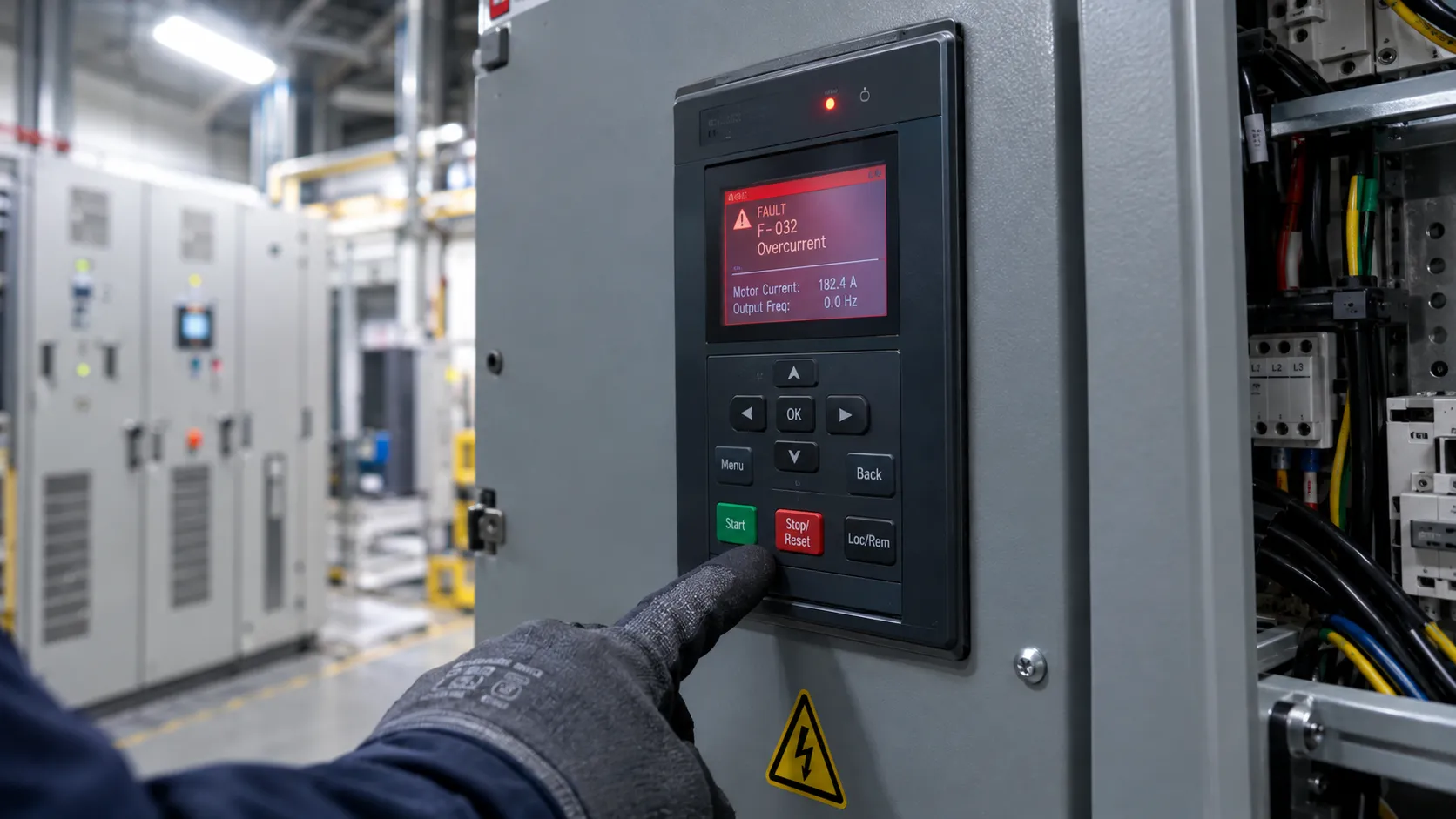
A motor hits the start command, the contactor closes, and before the shaft reaches running speed the drive faults out. The display shows an overcurrent code, the line stops, and whoever is standing at the panel wants it running again in five minutes. A VFD overcurrent trip at startup is one of the most common reasons a maintenance desk calls in outside help, and in most cases the drive did exactly what it was built to do: it protected its own power semiconductors from a current level that would have destroyed them in milliseconds. The real question isn't whether the trip was genuine. It's why the current got there, because resetting the fault and starting again only tells you whether the fault is intermittent, not what caused it.
This piece works through that diagnosis the way a field engineer actually has to: what the drive's protection functions are measuring, the causes that account for almost every VFD overcurrent fault on rotating equipment, and a decision tree you can run at the panel with the fault log open.
Hardware Overcurrent Trip vs Software Current Limit: Two Different Protections
Every modern drive, ABB, Siemens, Schneider Electric, or Mitsubishi alike, runs two separate layers of current protection, and confusing them is the single biggest reason people troubleshoot the wrong thing when the display shows what everyone on the floor calls a VFD OC trip.
The hardware overcurrent trip is instantaneous. Current sensors on the output stage feed a comparator watching for a level high enough to damage the IGBTs, typically 150 to 200 percent of the drive's rated output current depending on manufacturer and frame size. Cross that threshold and the drive cuts the gate signals within microseconds and latches a fault; there is no ramping away from this one, because it protects silicon with little thermal mass that a single switching cycle can destroy.
The software current limit is different, even though operators often lump it under the same "overcurrent" umbrella. It's a continuously monitored loop, usually set at 100 to 150 percent of motor rated current, that the drive uses to avoid ever reaching the hardware trip point. As current approaches that programmed limit, the drive responds by holding frequency steady, stretching the ramp, or trimming output voltage, a behavior most vendors call current limiting or foldback and Mitsubishi labels stall prevention. Set correctly, it lets the motor accelerate right up against its current ceiling without tripping. Set wrong, it either folds back so hard the motor never finishes starting, or sits so loose that the hardware trip ends up doing its job instead. A VFD current limit setting that doesn't match the load is behind more nuisance trips than any component failure, and it's the single biggest reason a VFD trips on overcurrent at startup even on a drive that has run fault-free for years.
Why Every Motor Start Looks Like a Fault to the Drive
A squirrel-cage induction motor at standstill behaves like a transformer with a shorted secondary. The current it draws the instant voltage is applied is governed by locked-rotor impedance, not load, and for most general-purpose induction motors that figure lands around six to eight times full-load current, a range reflected in the NEMA MG 1 locked-rotor code letter tables and in the starting-current classes IEC 60034-12 defines for cage induction motors. A direct-on-line motor draws this straight from the supply network, and the breaker and contactor are sized to survive it for the few seconds a normal start takes, a tradeoff covered in our comparison of VFDs against soft starters for motor starting duty.
A VFD cannot do that. It delivers that same locked-rotor demand through semiconductors with a fraction of a breaker's thermal mass, while generating the output waveform itself. This is why a drive's starting current rating is typically only 150 percent of continuous output for one minute, not the 600 to 800 percent a line-started winding tolerates briefly. Every start, even a healthy one, pushes the drive into territory where a variable frequency drive overcurrent trip is one misjudged ramp away. Starting current is not the fault; it's the normal condition the drive has to manage without tripping.
Root Cause #1: Acceleration Time Shorter Than the Load Actually Needs
This is the most common root cause behind a VFD overcurrent fault during acceleration, often reported simply as VFD overcurrent during ramp up, and it is almost always a commissioning oversight rather than a hardware defect. The torque a motor must deliver during a ramp equals the load's own running torque plus the torque needed to accelerate the combined inertia of motor and load, per the standard relationship T = J × (dω/dt), where J is total inertia and dω/dt is angular acceleration. Program a ramp faster than the load's inertia can realistically absorb, and the drive has no choice but to draw more current to produce the torque the ramp demands.
Centrifugal fans, crushers, ball mills, large centrifuges, and high-inertia conveyor systems are the usual suspects, because their inertia is large relative to their running torque. A drive commissioned with a generic default ramp, often around 10 seconds out of the box, will frequently work fine on a small pump and trip immediately on a large fan or mill rotor with the same drive model and a similar motor frame size. The fix is rarely a parameter mystery; it is recalculating the ramp against the actual reflected inertia and running the number, not guessing. This is also behind most reports that a VFD trips on overcurrent at startup intermittently rather than every time: a colder lubricant, a heavier material load on a belt, or a deeper line voltage sag at start can be the difference between a ramp that just clears current limit and one that doesn't.
This pattern isn't brand-specific. Our ABB variable speed drive field selection, integration and troubleshooting guide covers this exact fault on a real ABB conveyor line; this piece builds the brand-agnostic decision tree instead.
Real-World Scenario: A Seized Idler Bearing on a Cement Plant Feed Conveyor
A raw-mill feed conveyor at a cement plant in South Africa had run for years without incident before it began tripping on overcurrent every time the shift crew tried to start it after a weekend shutdown. The electrical team's first move was to swap the drive, on the assumption that a VFD overload trip meant a failing drive. The replacement, a different unit entirely, tripped at exactly the same point in the ramp on the first attempt.
That repeatability was the real clue, available from the first trip. A fault that occurs at a different point on the ramp each time usually points to something electrical or thermal that's drifting. A fault that occurs at the identical point every single time, regardless of which drive is installed, is a mechanical signature. Disconnecting the gearbox coupling and rotating the drive pulley by hand confirmed it in under two minutes: one idler roller bearing, buried mid-span under the belt, had seized after water ingress during the shutdown, and the static friction it added exceeded what the motor could overcome within the programmed ramp time.
A drive that trips on overcurrent at the same instant on the ramp every time, across more than one drive, is not reporting an electrical fault. It is reporting a mechanical one wearing an electrical fault code.
Replacing the idler bearing resolved the fault, with the original drive reinstalled and no parameter changes made. The lesson extends beyond conveyors: jammed positive-displacement pumps, seized motor bearings, and material packed into a stalled screw conveyor all present as an overcurrent fault during acceleration, because added mechanical friction and load inertia look identical to the drive. Bar the shaft by hand before accepting a parameter explanation for a fault that repeats at a fixed point on the ramp.
Root Cause #2: Wrong Motor Data Programmed Into the Drive
Open-loop volts-per-hertz control and closed-loop vector control both depend on an accurate motor data set entered at commissioning: rated voltage, current, frequency, speed or pole count, and ideally an autotune that characterizes stator resistance and leakage inductance directly rather than relying on nameplate assumptions. When that data doesn't match the motor actually connected, the drive's internal current and torque calculations work from the wrong reference, and its overcurrent and overload thresholds shift with them.
This shows up after a motor swap where the replacement carries a different nameplate current, after a rewind that changes winding resistance and inductance without changing the nameplate, or when a technician enters line current instead of the motor's rated phase current on a non-standard winding. A rotational or stationary autotune, run after any motor change and not just during the initial drive commissioning, catches this before it becomes a trip. Skipping it is a common reason a VFD fault troubleshooting session on a known-good drive and known-good motor turns up nothing obviously wrong with either component.
Root Cause #3: V/Hz Boost Set Too Aggressively for a High-Inertia Load
Open-loop volts-per-hertz control adds a boost voltage at low output frequency to compensate for the voltage dropped across stator resistance, since without it a motor would have no usable torque at the bottom of the frequency range. Trouble starts when that boost is set higher than the motor and load need. Excess boost in the first few hertz of the ramp, before the motor has built meaningful back electromotive force, drives magnetizing current up without a proportional gain in usable torque, and on a high-inertia load drawing hard to accelerate, that extra current can be enough to cross the limit threshold.
This is the scenario where an inverter overcurrent trip at motor start traces back to a parameter set during a rushed commissioning rather than to the load or the motor. Reducing boost to the minimum that still produces a clean, non-stalling start is usually sufficient, but high-inertia loads needing strong, precise low-speed torque, large centrifuges and extruders among them, are better served by switching from open-loop V/Hz to closed-loop vector control, which regulates torque-producing and flux-producing current separately rather than applying a flat voltage boost. Vector control needs an accurate motor model and, for best performance, an encoder, so it isn't a free upgrade, but on a load still nuisance-tripping under V/Hz control despite a properly sized ramp, it's usually the correct fix.
Root Cause #4: Cable and Motor Insulation Faults
A phase-to-phase or phase-to-ground fault inside the motor windings or feeder cable presents differently from the causes above, and the timing is the tell. Mechanical and ramp-related trips happen partway through acceleration, at a point tied to speed or torque demand. An insulation fault trips within the first electrical cycle or two, often before the rotor has turned at all, because the short-circuit path exists the moment voltage is applied, independent of speed.
Confirming this means disconnecting the motor from the drive output terminals and megger testing the windings and feeder cable separately, following the insulation resistance procedure in IEEE Std 43, with a polarization index check added for larger medium-voltage machines. Long cable runs between drive and motor, common on outdoor pump and compressor installations across Gulf sites and on spread-out yard equipment in Russia and South Africa, add a separate risk: reflected-wave voltage doubling at the motor terminals from impedance mismatch, which stresses winding insulation over months and can produce a fault that looks electrical but started as a cable coordination problem. Output reactors or dV/dt filters address this at the design stage; a motor testing and insulation resistance program catches it before it becomes an unplanned trip.
OC1, OC2, and What the Fault Phase Is Telling You
Mitsubishi's FR-series drives label this timing distinction directly in the fault code, and it's worth understanding even on other brands because the logic transfers. Per Mitsubishi's own documentation, E.OC1 indicates an overcurrent shutoff during acceleration, E.OC2 during constant-speed running, and E.OC3 during deceleration, each triggered around 200 percent of the drive's rated current. The phase is the diagnostic shortcut: a VFD OC1 fault implicates the start itself, meaning ramp time, load torque, or locked-rotor current. A VFD OC2 fault implicates something that changed mid-run: a load surge, a bearing beginning to seize, or a developing single-phasing condition. An OC3-equivalent fault implicates the stop, usually a deceleration ramp too short for the load's inertia without enough braking resistor or DC bus regulation to absorb the regenerated energy. The two point in completely different directions, which is why the fault log's phase-of-trip entry matters more than the code number itself.
Other manufacturers don't always split the code three ways, but every drive's fault log records which phase the trip happened in, and that detail narrows the root-cause list faster than any other step at the panel. Whether the display reads an ABB VFD overcurrent fault, a Siemens VFD overcurrent fault, a Schneider VFD overcurrent trip, or a Mitsubishi VFD overcurrent fault, the logic transfers even though the naming doesn't.
| Brand and Drive Family | Typical Overcurrent Fault Indication | What It Generally Flags |
|---|---|---|
| ABB (ACS880 platform) | Fault 2310, documented in the drive's own fault tracing manual | Output current exceeded the drive's internal overcurrent trip limit |
| Schneider Electric (Altivar series) | OCF on current Altivar drives; older Altivar 31/71 use O.CF | Output current exceeded the configured overcurrent limit |
| Mitsubishi Electric (FR series) | E.OC1 / E.OC2 / E.OC3 | Overcurrent shutoff during acceleration, constant speed, or deceleration, around 200 percent rated current |
Treat this table as orientation on VFD trip codes overcurrent, not a complete VFD fault codes list; it states only codes confirmed against each manufacturer's own documentation. Numbering isn't standardized even inside one brand: ABB's older ACS355 uses a different code than the ACS880 platform's 2310, and Siemens SINAMICS drives run their own list that shifts between the G120 and S120 families and firmware revisions, with sources disagreeing on whether a given Siemens code means overcurrent or an unrelated overspeed fault. Never carry a fault number over from a different drive or firmware revision; the drive's own fault manual is the final word.
A Field Decision Tree for a VFD Overcurrent Trip
Run these checks in order to troubleshoot VFD trip conditions before changing any parameter. Most VFD fault troubleshooting sessions that drag on for days skip step one and jump straight to guessing at parameters.
- Pull the fault log, not just the live display, and confirm which operating phase the trip occurred in: first cycle, partway through acceleration, steady running, or deceleration.
- Trips in the first electrical cycle, before the shaft visibly turns: isolate the motor from the drive output and megger test the windings and feeder cable separately. Suspect an insulation fault first.
- Trips at a repeatable point partway through the ramp, every time: bar the shaft by hand or disconnect the coupling and check for free rotation. Suspect a mechanical jam, a seized bearing, or packed material before touching a parameter.
- Load rotates freely by hand: temporarily extend the ramp as a diagnostic step only. If that clears the fault, it's inertia versus ramp time, a genuine VFD acceleration time overcurrent problem, and the permanent fix is a longer calculated ramp, a boost or vector-control adjustment, or in marginal cases a larger drive frame.
- Trip happens during steady running, not the start, so the VFD trips on load rather than inertia: investigate load surges, incoming supply quality, single-phasing, and developing bearing wear.
- Trip happens during deceleration: check the stop ramp against load inertia and confirm the braking resistor or DC bus regulation is sized for the returned energy.
- Confirm the motor nameplate data programmed into the drive matches the motor installed, and run an autotune if there's any doubt or history of a swap or rewind.
- Only after the above are clear, review the VFD current limit setting against the motor's actual full-load current and the starting duty, rather than adjusting it first and hoping.
Setting the Current Limit to Stop VFD Nuisance Tripping
The instinct when a drive won't stop tripping is to raise the current limit until it stops complaining. That instinct causes real damage: it treats a VFD current limit fault as a parameter nuisance rather than information. The current limit function exists to stop the drive before it reaches a condition the motor, cable, or mechanical system can't handle. Raising it blindly past that point doesn't fix anything; it removes the early warning while leaving the overheating winding, the degrading bearing, or the undersized feeder cable exposed.
A workable starting point sets the current limit with margin over the motor's actual full-load current, not the drive's rated current, verified against the drive's and motor's thermal withstand data. High-inertia or frequent-start applications need an engineered ramp-and-torque calculation behind that number, not a guess, because the current limit interacts with ramp time: loosen one without checking the other and a nuisance trip becomes thermal damage that won't show up for months. Root cause first, parameter second. A current limit adjusted after confirming the ramp, the motor data, and the mechanical condition are correct is a tuning decision that belongs inside an ongoing electrical maintenance and reliability program. One adjusted before checking any of that is a guess that makes the fault go away today and sets up another VFD overcurrent trip down the line.
Field troubleshooting an intermittent VFD overcurrent trip is rarely a one-visit job, and ending VFD nuisance tripping for good means finding a root cause that can sit anywhere from winding insulation to a mechanical load to a parameter set years ago at commissioning. Techno Control Corporation's variable frequency drive engineers bring the drive-specific diagnostic software, insulation test equipment, and load-torque calculation background needed to separate a genuine electrical fault from a mechanical one hiding behind an overcurrent code, size replacement drives and soft starters correctly when a frame upgrade is the real fix, and verify the fix holds under full production load, not just a no-load test run.
Frequently Asked Questions
Why does my VFD trip on startup with an overcurrent fault?
Most startup trips come down to one VFD overcurrent cause from a short list of five: an acceleration ramp shorter than the load's inertia can absorb, a mechanical jam or seized bearing presenting as an electrical fault, incorrect motor nameplate data programmed into the drive, V/Hz boost set too high for a high-inertia load, or a winding or cable insulation fault. Locked-rotor current itself, typically six to eight times full-load current, is normal; the drive's job is managing that current without crossing its hardware or software limit.
What is the difference between an OC1 and OC2 fault?
On Mitsubishi FR-series drives, E.OC1 is an overcurrent shutoff during acceleration and E.OC2 is the same protection tripping during constant-speed running, each around 200 percent of rated current. A VFD OC1 fault points to the start itself: ramp time, load torque, or locked-rotor current. A VFD OC2 fault points to something that changed mid-run, such as a load surge, a developing bearing failure, or single-phasing.
How do I stop VFD nuisance tripping?
Don't raise the current limit first. Pull the fault log to confirm which phase of operation the trip occurs in, rule out a mechanical jam by barring the shaft, confirm the motor nameplate data and autotune are correct, and only then adjust the ramp, boost, or current limit with the mechanical and electrical causes ruled out. Raising the limit before that just removes the early warning the trip was giving you.
What VFD current limit setting prevents overcurrent trips?
There's no universal VFD overcurrent protection setting. The current limit needs margin over the motor's actual full-load current, verified against the drive's and motor's thermal withstand data rather than the drive's own rated current. Standard starting duty usually needs less margin than a high-inertia or frequent-start application, which needs an engineered ramp-and-torque calculation behind the number rather than a guess.
Related products
Components from our catalogue relevant to this article — request a quote for availability, lead time and pricing.
/TC625 AF100 ABB - Coaxial Modem 3BSE002224R1.png "ABB TC625 AF100 ABB - Coaxial Modem 3BSE002224R1 | Coaxial modem TC625 AF100")
TC625 AF100 ABB - Coaxial Modem 3BSE002224R1
Coaxial modem TC625 AF100
/SB512 ABB - Power Supply 3BSE002098R1.png "ABB SB512 ABB - Power Supply 3BSE002098R1 | SB512 power supply module")
SB512 ABB - Power Supply 3BSE002098R1
SB512 power supply module
/DSSS 171 ABB - Voting Unit 3BSE005003R1.png "ABB DSSS 171 ABB - Voting Unit 3BSE005003R1 | DSSS 171 voting unit for safety systems")
DSSS 171 ABB - Voting Unit 3BSE005003R1
DSSS 171 voting unit for safety systems
/4NWP100174R0001 ABB - UPS PowerValue 11LI Up 2000 VA.webp "ABB 4NWP100174R0001 ABB - UPS PowerValue 11LI Up 2000 VA | UPS PowerValue 11LI Up 2000 VA")
4NWP100174R0001 ABB - UPS PowerValue 11LI Up 2000 VA
UPS PowerValue 11LI Up 2000 VA