
Safety Interlock Switches: How Guard Locking and Standstill Monitoring Keep a Guard Shut Until Motion Stops

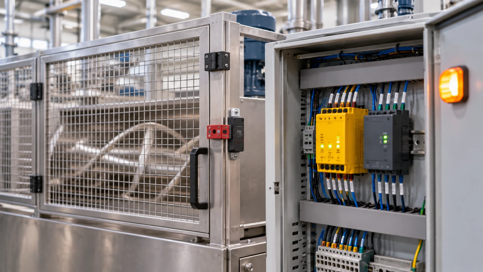
Quick Answer
A safety interlock switch stops a machine when a guard opens, and guard locking keeps the guard shut until the motion has stopped. Here is how solenoid interlocks, standstill monitoring and safety relay modules work together.
An operator opens a guard door on a mixer, the machine stops, and the operator reaches in. The drum is still turning. It was switched off, but a heavy drum coasts for many seconds, and the operator's arm is in the machine before the motion has finished. This is the classic gap in machine safety: stopping a machine and the machine being stopped are not the same event, and a guard that opens at the first moment gives access during the second.
A safety interlock switch is a switch on a movable guard that sends a stop signal to the machine's safety circuit when the guard opens, so that the hazard is removed before anyone can reach it. Where the machine takes time to stop, the interlock is combined with guard locking, which keeps the guard closed until the motion has ended, and with standstill monitoring, which confirms the end. This guide explains how a safety interlock switch works, how a solenoid interlock switch locks a guard, how a door interlock switch differs by type and coding level, how standstill monitoring releases the lock at the right moment, and where a safety relay module fits, with Schmersal devices as the examples.
The Hazard That Outlasts the Stop Command
A machine does not stop when the power goes. Inertia keeps a rotating part moving, and stored energy in a hydraulic accumulator, a spring or a raised load keeps other parts moving too. A saw blade, a centrifuge, a mixer drum and a grinding wheel can each coast for seconds or minutes after the motor is cut, and during that run-down the hazard is as real as at full speed.
An interlock that only monitors whether the guard is open gives no protection against this. The guard opens, the circuit trips, and the guard is free to be pulled wide at once. Guard locking changes that: a bolt or a solenoid holds the guard shut until a release condition is met, either a time delay long enough to cover the run-down or, better, a signal from a standstill monitor that the motion has stopped.
The distinction counts most where machines vary. A time delay set for one load condition is wrong for another: a mixer drum coasts longer empty than full, and a saw coasts longer on a new bearing than a worn one. A standstill monitor reacts to the real state of the machine, so designers use one wherever dangerous overrunning movement is expected.
How a Safety Interlock Switch Works
A safety interlock switch has two parts: a body on the fixed frame and an actuator on the moving guard. When the guard closes, the actuator engages the body and the safety contacts close. When it opens, the contacts open, and the safety circuit trips. The device is built to fail towards the safe state.
Three design features set a safety switch apart from an ordinary limit switch. The contacts are positive break, also called direct opening: a spring-pushed contact can weld shut and stay closed, but a positive-break design uses the actuator's motion to force the contact open mechanically. Two independent channels are used, so one failure does not lose the safety function, and the controller monitors the two for agreement. And the device resists defeat: the actuator is coded so that a loose piece of metal or a spare key cannot replace it.
Non-contact designs use magnetic or RFID coding instead of a mechanical tongue. The body detects a coded actuator without touching it, which tolerates misalignment and allows a sealed housing that washes down cleanly. The Schmersal RSS 36, for example, is an RFID safety sensor with two PNP safety outputs, rated to category 4 and SIL 3, and up to 31 can be connected in series. Mechanical tongue switches remain common where toughness counts and cost is tight.
A guard that opens the moment the stop button is pressed protects nobody from a machine that is still turning. The interlock has to wait for the motion, not for the command.
Guard Locking and the Solenoid Interlock Switch
A solenoid interlock switch is a safety switch with a locking mechanism. A bolt or a cam, driven by a solenoid and a spring, holds the actuator in the body, and the guard cannot be opened until the lock releases. The same device usually also carries the safety contacts that signal guard position and lock state, which is why a solenoid interlock switch counts as a safety interlock switch with a lock added.
Every interlock safety switch with a lock has to answer one design question: how does the lock behave on power failure? In a spring-applied design with power to unlock, a spring holds the guard locked, and the solenoid must be energized to release it. If the supply fails, the guard stays locked, which is the safe default where the hazard is still present. In a power-to-lock design, the solenoid holds the lock, and a power failure releases the guard. That suits process protection, or a walk-in enclosure where a trapped person must be able to escape, and the standard treats it with caution for personnel protection: it is acceptable only where a risk assessment shows that unlocking on power loss cannot expose anyone to the hazard.
The Schmersal AZM201Z in the TCC catalog is a typical personnel-protection device: an RFID-coded solenoid interlock with power to unlock, a holding force of 2000 N, OSSD safety outputs that allow series wiring up to 200 m, and IP66 and IP67 sealing, for hinged and sliding guards. The AZM 170SK is a compact relative with 1000 N holding force and an IP67 housing. A heavy guard that bounces on its hinge, or that people lean against, needs a strong lock.
Many devices include an escape release so that a person trapped inside the guarded area can open the door from within, and a manual release for maintenance when the power is off. Fit the escape release wherever trapping is possible, such as a walk-in enclosure.
Door Interlock Switch Types and Coding Levels
Selecting a door interlock switch, or any interlock safety switch, starts with the guard: hinged, sliding or removable, how far it moves and how heavy it is. EN ISO 14119 sets the principles for interlocking devices on guards and classifies them by type and by coding level, which measures how hard the device is to defeat.
| Type | How it detects | Strengths | Limits |
|---|---|---|---|
| Mechanical tongue switch | Coded tongue enters the body | Tough, tolerant of dirt, low cost | Needs aligned fit, can be defeated with a spare tongue |
| Magnetic non-contact | Magnet in the actuator | Sealed, tolerant of misalignment, cheap | Low coding, easy to defeat with a magnet |
| RFID non-contact | Coded transponder | High coding, sealed, washable, series wiring | Higher cost |
| Hinge or cam-operated | Position of a hinge or cam | Compact on hinged guards | Defeat resistance depends on the mounting |
Coding level separates one device from another. The standard defines low, medium and high levels by the number of coding variants: low means one to nine, medium ten to one thousand, and high more than a thousand. A magnetic switch with a universal actuator is low, because any matching magnet works, while an RFID switch with individually taught actuators is high. Plants with a history of bypassed guards should choose a high level with individual coding.
A door interlock switch with diagnostics reports a misaligned guard before it causes a stoppage, which reduces the temptation to defeat it.
Standstill Monitoring: Releasing the Lock at the Right Moment
Standstill monitoring is the function that confirms the hazardous motion has stopped, and it releases the guard lock only then. Four approaches exist, in order of increasing sophistication.
A time delay relay is the simplest. The release waits a fixed time, set longer than the worst-case run-down. It is cheap and acceptable where the run-down is short and predictable, and it fails where the run-down varies or where someone shortens the delay to save time.
Sensor-based standstill monitoring reads the actual motion. A proximity sensor or an encoder on the shaft gives a pulse train, and the monitor decides that the shaft has stopped when the pulses cease. The Schmersal FWS 3505C in the catalog is of this type, taking two pulse sensors, with a standstill frequency threshold of 1 Hz and four enabling paths.
Sensorless standstill monitoring measures the residual voltage that a coasting motor produces at its terminals, the back-EMF, and releases when it falls below a threshold. It needs no sensor on the shaft, which makes it easy to retrofit. The Schmersal SSW303HV-2S in the catalog works this way, connects directly to motors up to 690 V, and carries three safety contacts for category 4 and performance level e. Whether it suits an installation depends on the motor and the drive: a motor held by a brake, or turned through a gearbox without producing voltage, may give no signal, so the manufacturer's application notes list the cases it covers.
Drive-based safety functions are the fourth approach. Modern variable frequency drives carry Safe Torque Off and often Safe Stop 1, which ramps the motor down and then removes torque, with standstill detection built in. The drive systems in our catalog, such as the Altivar Process ATV960, list STO to SIL 3, and the range described in our article on the main types of Schneider frequency inverters shares that approach. Using the drive's own function removes an external module, provided the drive's safety function is wired and validated to the required performance level.
The Safety Relay Module in the Chain
A safety function has three parts: an input device that detects, a logic unit that decides, and an output device that acts. The interlock switch is the input. The output is a contactor that removes power or a drive's STO input. The safety relay module is the logic in between, in the simple case, and it does a precise job.
A safety relay module monitors the dual channels from the interlock for faults such as a short between them or a stuck contact, and it energizes its force-guided output contacts only when both channels agree. It handles the start condition, either automatic start when the guard closes or manual start by a reset button with monitored reset, so a stuck button cannot restart the machine. It also handles the type of stop: STOP 0 cuts power at once, and STOP 1 allows a controlled stop first, then removes power after a delay.
Schmersal's SRB series illustrates the range. The SRB301LC has three safety contacts for STOP 0, rated to performance level e and category 4, for emergency stops, guard switches, magnetic switches and light curtains. The SRB324ST combines STOP 0 contacts with delayed STOP 1 contacts, and the SRB402EM adds contacts as an expansion module. Select a module for the number and type of inputs, the stop types, the contact ratings and the performance level it supports. Large or complex machines use a safety PLC instead, which handles many functions in software.
Standards: EN ISO 14119, ISO 13849-1 and IEC 60204-1
Three standards frame the work. EN ISO 14119 covers interlocking devices associated with guards, including types, coding, guard locking and defeat prevention. ISO 13849-1, in its 2023 edition, defines how to assess the reliability of the safety function by performance level, from a to e, which depends on the circuit structure (category), component reliability, diagnostic coverage and common cause failure measures. IEC 60204-1 covers the electrical equipment of machines, including the stop categories: category 0 removes power at once, category 1 brings the machine to a controlled stop and then removes power, and category 2 keeps power on after the stop.
The risk assessment sets the required performance level, using ISO 12100 and the tables in ISO 13849-1. A guard on a machine with a risk of serious injury needs performance level d or e, which in practice means a coded interlock, redundant monitoring, a safety relay or safety PLC, and often guard locking. The law behind these standards varies. In the UK, the Provision and Use of Work Equipment Regulations 1998 require dangerous parts of machinery to be guarded. In the United States, OSHA's machine guarding rules in 29 CFR 1910.212 apply, together with ANSI B11 standards. In the European Union, the Machinery Directive 2006/42/EC is replaced by the Machinery Regulation (EU) 2023/1230, which applies from 20 January 2027. Our post on AI in manufacturing and safety compliance shows how the same standards bear on newer technologies.
Common Mistakes: Defeat, Series Wiring and Wrong Release Logic
Defeat is the largest day-to-day problem. Operators bypass interlocks when they slow work down, by taping a magnet to a switch, leaving a spare actuator in the body or jumpering the contacts in the cabinet. Coded actuators and hidden mounting make that harder, but the fix that works is to make the guarded task faster with the guard than without it, and to supervise the machine.
Series wiring is next. Many interlocks can be wired in series to one safety input, and a fault in one device can be masked by the others, which reduces diagnostic coverage and can lower the achievable performance level. Devices with OSSD outputs and built-in diagnostics reduce the problem, and the standard limits how far series connection can go at high levels.
Wrong release logic is the third. A time delay shorter than the real run-down is the commonest, and it appears when a machine is modified, a heavier rotor is fitted or a brake wears. Measure the run-down by test at the worst case, add margin, and prefer a standstill monitor where it varies. A power-to-lock device on a coasting machine is another fault, as are release conditions that depend on a single channel. A radar or optical presence sensor is no substitute for an interlock either: our post on radar sensors notes that standard industrial radar units are not safety devices.
Real-World Scenario: A Mixer That Opened Too Soon
This case is an illustration. A food plant runs a 15 kW ribbon mixer behind a hinged guard with a door interlock switch and a timer set to release after 10 seconds. The mixer was tested with a full load, which stops in about 6 seconds. In normal use, operators often run the mixer partly full or empty to clean it, and an empty ribbon stops after more than 20 seconds. Twice, an operator opened the door after 10 seconds and found the ribbon still turning. Nobody was hurt, and the near miss triggered a review.
The review finds that the fault is in the design, not in the operators. The timer matched one test condition, and the plant had never measured the empty case. The fix replaces the timer with a solenoid interlock switch with power to unlock and RFID coding, wired to a safety relay module, with a sensorless standstill monitor connected to the motor terminals. The relay's contacts release the lock only when the monitor reports standstill, so a drum that coasts for 6 seconds or 26 seconds is released at the correct moment either way.
The plant then validates the system. Operators try to open the door while the mixer is running, coasting and stopped. The release time is measured in the empty and full conditions, and the system is documented with the performance level calculation, the wiring diagram and the test record.
Selecting, Validating and Testing
A selection starts with the risk assessment. List each hazard behind the guard, estimate the run-down time under the worst condition, and determine the required performance level. Choose the safety interlock switch type and coding level that suit the guard and the defeat risk, and a solenoid version where the run-down is longer than the time to reach the hazard. Then choose a standstill method that suits the motor and the drive, and the safety relay module or safety PLC that supports the performance level.
The Schmersal AZM201Z RFID solenoid interlock and the Schmersal SSW303HV-2S standstill monitor in the TCC catalog are one matched pair for this job, and the SRB relay range completes the chain. Validation then proves the whole function, not the parts: operate the guard in every state, confirm the lock holds while the machine runs and releases only at standstill, simulate a wire break and a stuck contact, and record the results. Repeat a short function test at each shift start for frequently used guards, and run a full validation after any change to the machine, the drive or the wiring.
TCC's industrial automation and electrical engineering teams supply, wire and validate interlocks, standstill monitors and safety relays, and document the performance level calculations. The commissioning approach in our guide to LV panel commissioning tests applies to the safety panel in the same way as to the power panel.
Frequently Asked Questions
What is a safety interlock switch?
A safety interlock switch is a switch fitted to a movable guard that signals the machine's safety circuit when the guard opens, so the hazard is removed before anyone can reach it. It uses positive-break contacts, usually two channels and a coded actuator that resists defeat. Some versions add a solenoid that locks the guard.
What is the difference between a safety interlock and a solenoid interlock switch?
A basic safety interlock only detects whether the guard is open or closed. A solenoid interlock switch also locks the guard shut with a bolt and a solenoid until a release signal arrives. Locking is needed where the machine keeps moving after it is switched off, since the guard must stay closed until the motion has stopped.
What is standstill monitoring?
Standstill monitoring is a safety function that detects when a machine's hazardous motion has stopped and then allows the guard lock to release. It can use a sensor or encoder on the shaft, measure the back-EMF of the coasting motor without a sensor, or use the drive's own safety function. It is more reliable than a fixed time delay, because it follows the real run-down.
What does a safety relay module do?
A safety relay module is the logic unit between the interlock switch and the contactor or drive. It monitors the two channels from the switch for faults, energizes its force-guided output contacts only when the inputs are valid, manages automatic or manual reset, and provides STOP 0 or delayed STOP 1 outputs. Its rated performance level sets a limit on the whole safety function.
Related products
Components from our catalogue relevant to this article — request a quote for availability, lead time and pricing.
/103037586 Schmersal - SSW303HV-2S.webp "Schmersal Schmersal SSW303HV-2S Standstill Monitor, Sensor-Free | Fail-safe standstill monitor via motor EMF, up to 690 V, 2 s, 3 safety contacts, PL e")
Schmersal SSW303HV-2S Standstill Monitor, Sensor-Free
Fail-safe standstill monitor via motor EMF, up to 690 V, 2 s, 3 safety contacts, PL e
/103044808 Schmersal - AZM201Z-I2-ST2-T-1P2PW-DU.webp "Schmersal Schmersal AZM201Z-I2-ST2-T-1P2PW-DU RFID Solenoid Interlock | RFID-coded solenoid interlock, power to unlock, 2000 N holding force, OSSD, IP66/IP67")
Schmersal AZM201Z-I2-ST2-T-1P2PW-DU RFID Solenoid Interlock
RFID-coded solenoid interlock, power to unlock, 2000 N holding force, OSSD, IP66/IP67
/AZM 170SK-11 02ZRKA 24VAC DC Schmersal.webp "Schmersal Schmersal AZM 170SK-11/02ZRKA 24 VAC/DC Solenoid Interlock | Compact solenoid interlock, 1000 N, 24 VAC/DC solenoid, positive break contacts, IP67")
Schmersal AZM 170SK-11/02ZRKA 24 VAC/DC Solenoid Interlock
Compact solenoid interlock, 1000 N, 24 VAC/DC solenoid, positive break contacts, IP67
/FWS 3505C-2204 Schmersal.webp "Schmersal Schmersal FWS 3505C-2204 Standstill Monitor, 2 Pulse Sensors | Standstill monitor with 2 pulse sensors, 4 enabling paths, 1 Hz standstill, 24 VDC")
Schmersal FWS 3505C-2204 Standstill Monitor, 2 Pulse Sensors
Standstill monitor with 2 pulse sensors, 4 enabling paths, 1 Hz standstill, 24 VDC