
LV Panel Commissioning Tests: What to Check Before You Energize

Quick Answer
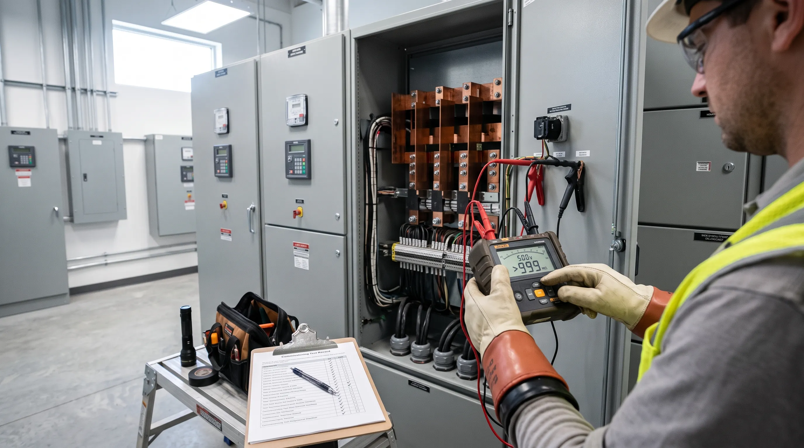
LV panel commissioning tests follow a fixed sequence: visual inspection, insulation resistance, continuity and earth bonding, polarity, functional checks, and protection settings verified against the coordination study, before the panel is energized.
A low voltage panel that sails through the builder's shop floor can still fail the first time someone closes the main incomer on site, and that gap is rarely a defect nobody could have caught. It is a step in the LV panel commissioning tests sequence that got skipped, rushed, or signed off on trust instead of a reading. Commissioning is not one inspection; it is a fixed order of checks, each one gating the next, confirming a switchboard built to a drawing is safe to energize and will do what the drawing says it will do.
That LV switchgear commissioning sequence is the same whether the panel is a 400 A distribution board or a 4000 A main switchboard: visual and mechanical inspection, insulation resistance testing, continuity and earth bonding verification, polarity checks, functional and interlock testing, protection settings verified against the coordination study, and, where the design calls for it, primary or secondary injection testing. Two distinct events bracket that sequence: the Factory Acceptance Test (FAT) at the builder's premises, and the Site Acceptance Test (SAT) once installed, before energizing. Treating one as a substitute for the other is where avoidable site problems start.
IEC 61439-2 defines the switchboard as a power switchgear and controlgear assembly (a PSC-assembly), covering equipment rated up to 1000 V AC or 1500 V DC. IEC 61439-1 carries the general rules both parts share, including the verification clauses this piece works through. Motor and VFD panel selection is a different scope question, covered separately in medium voltage motor VFD panel selection. In the United States, the equivalent reference is ANSI/NETA ATS, covering switchgear, switchboards, and panelboards built to UL 891 or UL 1558 rather than IEC 61439, so the panel commissioning procedure IEC 61439 prescribes for a Gulf, Russian, South African, or UK project needs translating, not copying, for a US-code job. The panel commissioning checklist changes in a few places as a result.
Visual and Mechanical Inspection Against the Approved Drawing
This is where every LV panel inspection checklist starts, and it is the stage most often rushed because nothing on it looks like a "real" test. That is a mistake: a wiring error, a missing barrier, or a wrong-rated component caught here costs minutes; caught after energizing, it costs a shutdown.
The inspector works from the approved-for-construction drawing, not the tender drawing. Items to confirm: component ratings match the single-line and schematic (breaker frame and trip rating, contactor coil voltage, relay model); busbar sizing and phase clearances match the design calculation; IP rating matches the site's environmental classification; cable gland and termination sizes suit the conductors landed; nameplate and labeling data match the equipment installed; and mechanical fixings (busbar supports, door hinges, earth bars) are torqued to the builder's values, not finger-tight. Any deviation gets written up before testing continues, because every downstream test assumes the as-built configuration matches the design the protection settings and insulation calculations were based on.
This is also where degree-of-protection verification against IEC 60529 happens, and where segregation between functional units is confirmed against the Form of internal separation specified (Form 1 through Form 4b under IEC 61439-2), which matters for arc containment and future maintenance access alike.
Insulation Resistance Testing: What Actually Counts as a Pass
An insulation resistance test panel result is the single most referenced number in any set of LV panel commissioning tests, and also the most commonly misquoted, because two different standards set two different thresholds for two different things.
IEC 61439-1's routine verification clause (11.9, dielectric properties) lets the builder substitute an insulation resistance measurement for a full power-frequency withstand test, but only for assemblies with incoming protective device ratings up to 250 A, at a measuring voltage of at least 500 V DC. The pass criterion is a minimum of 1000 ohms per volt of supply voltage to earth, measured circuit by circuit with all breakers closed and sensitive electronics (surge arresters, trip units, communication modules) disconnected so they are not damaged by the test voltage and do not mask a real fault with their own leakage path. That is a factory-level, per-circuit routine test, and it is what generates the electrical panel factory acceptance test's insulation record.
A separate figure applies once the panel is installed as part of an electrical installation rather than tested standalone. IEC 60364-6 sets the acceptance table most site engineers quote: up to 500 V, test at 500 V DC, accept 1 MΩ minimum; above 500 V up to 1000 V, test at 1000 V DC, accept 1 MΩ minimum; for SELV/PELV circuits, test at 250 V DC, accept 0.5 MΩ minimum. Those are floor values, not target values. A new, dry, clean LV panel typically reads in the hundreds of megohms to multiple gigohms on a calibrated megger. A reading in the low single-digit megohms on a brand-new board that technically clears the 1 MΩ floor is not a pass worth accepting quietly; it usually means moisture, surface contamination, or a partially seated connector, cheaper to chase down in the test bay than after a year in service.
A new panel reading just above the 1 MΩ floor isn't a pass. It's a defect that hasn't finished announcing itself.
Run the electrical panel megger test phase-to-phase, phase-to-earth, and neutral-to-earth, with the voltage applied long enough to stabilize (commonly 60 seconds, recording the 15-second and 60-second readings to calculate a polarization index on larger assemblies). Record ambient temperature and humidity alongside every reading, since insulation resistance falls with both; comparing FAT and SAT readings taken under very different conditions without that context is not fair. The same underlying physics, a DC test voltage and a leakage-current reading, is what we've covered for motor and transformer winding insulation testing; a switchboard's geometry is simpler, but an insulation resistance test panel result is read against the same rule: the number only means something next to its own baseline, not just the code floor.
Continuity and Earth Bonding Verification
The LV panel continuity test confirms that every exposed conductive part inside the enclosure (gland plates, mounting rails, door frames, instrument panels) is bonded back to the main earth bar through a low-impedance path, not merely touching a painted frame. It is tested with a low-resistance ohmmeter that injects enough current, typically several amps, to produce a stable, repeatable reading. A standard multimeter on its resistance range reads the right ballpark on a good bond and can still pass a loose, high-resistance crimp that a real fault current would turn into an arcing point.
IEC 61439-1's routine verification requires this check on every assembly before it leaves the factory, and the SAT repeats it after installation, because site earthing (the panel's earth bar out to the facility's earthing system) is new scope the FAT never saw. Code basis genuinely diverges by region: IEC 60364-5-54 governs protective bonding and earthing arrangements (TN-S, TN-C-S, TT, IT) across most of the Gulf, Russia, South Africa, and the UK, while a US-code panel follows NEC Article 250 and the single-point neutral-ground bonding rule covered in our piece on how the TN system in American panels keeps neutral and ground tied at one point. A low voltage panel commissioning checklist written for an IEC job and reused unmodified on a US-code project will miss the site-specific bonding checks the NEC requires.
Polarity Checks
Polarity testing confirms that every switching device (breaker, contactor, fuse) actually interrupts the line conductor it is meant to interrupt, and that single-pole protective devices are never wired into the neutral. It sounds basic, and it is still a common field finding on a switchboard commissioning checklist, usually traced to a wiring error made months earlier that nothing else in the sequence would have caught.
The check also covers phase sequence: confirming L1, L2, L3 (or R, Y, B in some regional conventions) land on busbars in the same order across every outgoing way, verified with a phase rotation meter before any three-phase motor load is connected. Getting phase sequence wrong does not trip a protective device; it runs every motor on that board backward the first time it starts, a mechanical problem (reversed pumps, fans fighting their own design direction) disguised as an electrical one.
Functional and Interlock Testing
Functional testing exercises every control function the panel is built to perform: breaker close and trip from local and remote command, indication lamps and meters reading correctly, alarm relays operating on the conditions they are meant to detect, and control wiring matched against the schematic, a scope that often overlaps with our instrumentation and control work on the same panel. In MCC commissioning tests and on any switchboard with bus-tie logic, this stage also proves out electrical interlocking (preventing two incomers and a bus-tie from all closing onto a live bus at once) and mechanical interlocking (racking sequences on withdrawable breakers, door interlocks blocking access to live compartments). Our companion piece on what's actually inside a containerized MCC panel covers how that logic gets built up on a motor control center specifically.
This panel functional test checklist item genuinely needs two people: one operating commands, one confirming the physical response at the device, because a status light showing "closed" and a breaker actually being closed are not always the same fact after a control wiring fault.
Protection Device Settings Verification Against the Coordination Study
Every protective device in the panel (main incomer breaker, feeder breakers, motor protection relays) needs its settings checked against the protective device coordination (selectivity) study before the panel goes live, not against a generic default. The study is based on the actual available fault current at that point in the network (typically calculated to IEC 60909 or IEEE 551), and it exists so a fault downstream trips the nearest upstream device and nothing else. A panel commissioning test report confirming insulation resistance and continuity but never confirming the long-time, short-time, and instantaneous settings against that study has verified the panel is safe to touch, not that it behaves correctly under fault.
A panel frequently gets caught with as-shipped default settings active, either because the coordination study was issued after it left the factory, or a revision during construction never reached site. Confirming settings against the current revision, and recording that revision on the report, is cheap insurance against a miscoordinated trip, the gap our power system audits and protection coordination work usually finds.
Primary and Secondary Injection Testing
Secondary injection disconnects the protection relay from its current and voltage transformers and feeds it controlled test signals directly, confirming the relay trips at the correct current, time delay, and characteristic curve without passing real fault current through the breaker. Switchboard commissioning tests normally prove relay settings this way: fast, low-risk, and repeatable.
What secondary injection cannot confirm is the current transformer ratio, polarity, and the wiring path between the CT and the relay, since the CT itself is bypassed. Primary injection closes that gap: a high-current test set pushes actual current through the main circuit, the CT, and the relay under test, proving the entire path end to end rather than just the relay's response to a synthetic signal. It needs heavier equipment and more setup time, and carries real risk to a breaker not rated for repeated high-current cycling, which is why most LV panels default to secondary injection, reserving primary injection for critical incomers, bus-tie protection, or any circuit whose CT wiring cannot be visually confirmed with full confidence. A well-written panel commissioning procedure for an IEC 61439 project specifies which breakers get which method up front; it is not left to the technician's judgment on the day.
FAT vs SAT: Who Witnesses What, and What Gets Documented
These two events split the LV panel commissioning tests sequence by location rather than by test type. The Factory Acceptance Test happens at the builder's premises before shipment, and it is the builder's test to run, covering everything verifiable without the panel being installed: visual and mechanical inspection, insulation resistance and dielectric routine tests under IEC 61439-1, continuity of the protective circuit, functional operation of breakers and interlocks on the bench, and secondary injection of protection relays using the builder's test set. The FAT the LV panel undergoes before shipment is witnessed by the client's engineering representative or a third-party inspection agency named in the contract, and the signed FAT report becomes the baseline every SAT reading is compared against.
The Site Acceptance Test happens after installation and earthing, before energizing, and repeats the tests transport and site conditions can change: insulation resistance (to catch moisture ingress or a damaged cable during transit or pulling), continuity and earth bonding through to the site earthing system (not testable at the factory, since the site earth did not exist yet), polarity through the newly landed field cables, and a full functional test with actual field devices connected rather than the builder's test jig. The SAT the LV panel undergoes on site is normally witnessed by the client, the installing contractor, and often the panel builder's commissioning engineer, since any discrepancy between FAT and SAT readings needs someone who knows the original conditions to interpret it.
The FAT proves the panel was built right. The SAT proves it survived being delivered, installed, and connected to a site that did not exist when the FAT happened. Treating either as optional treats the other's result as more certain than it actually is.
Documentation from both stages belongs in one handover package: the drawing set, the FAT report with every reading and witness signature, the SAT report in the same format, the coordination study revision used for settings, and any punch list items closed between the two. That package is what a maintenance team references years later in a fault investigation.
| Test Stage | What It Verifies | Pass Criteria / Reference | Normally Witnessed By |
|---|---|---|---|
| Visual and mechanical inspection | Build matches approved drawing, labeling, torque, IP rating | IEC 61439-2 / IEC 60529 | Panel builder QA, client engineer |
| Insulation resistance | No leakage path phase-phase, phase-earth | 1000 ohms/V per circuit at FAT (IEC 61439-1); 1 MΩ min. at 500 V DC on site (IEC 60364-6) | Test technician, witness |
| Continuity and earth bonding | Low-impedance path, exposed metal to earth bar | Low-resistance ohmmeter | Test technician, witness |
| Polarity and phase sequence | Correct conductor interrupted, correct rotation | Phase rotation meter | Commissioning engineer |
| Functional and interlock test | Control logic, indication, interlocks | Approved control schematic | Two-person test |
| Protection settings verification | Relay/trip unit settings vs. coordination study | Latest study revision | Protection engineer |
| Secondary/primary injection | Relay response, and CT ratio/polarity/wiring | Relay test set; current injection set for primary | Protection/commissioning engineer |
A Real-World Scenario: The Desalination Plant Switchboard That Passed FAT and Failed SAT
The Setup
A desalination plant in the Gulf ordered a new 1600 A LV switchboard feeding a reverse osmosis train's pumps and auxiliary loads. The panel builder ran the full FAT program: visual inspection, insulation resistance readings in the gigohm range on every circuit, continuity checks, and secondary injection of the feeder relays. Every reading passed, the FAT report was signed, and the switchboard shipped by sea for the final leg of the journey.
What Went Wrong
The container sat at a transshipment port for nineteen days in a humid season, then the switchboard was stored outdoors, shrink-wrapped but without space heaters or desiccant running, for two more weeks before installation. When the site team ran insulation resistance as the first SAT step, one outgoing feeder read 2.8 MΩ phase-to-earth, technically above the 1 MΩ floor in IEC 60364-6, but two orders of magnitude below the FAT reading on that same circuit. Everything else read in the expected range.
The Fix
Rather than accept the technically passing reading, the commissioning engineer isolated the feeder, opened the gland, and found condensation inside a termination box sealed but not vented during humid storage. The termination was dried with low-level heating over 36 hours and re-tested, returning to a reading consistent with the other feeders. Energizing on the strength of the first SAT reading alone would have put a compromised termination into service on a feeder carrying a critical pump motor.
A reading that clears the code minimum and a reading that matches the equipment's actual condition are not the same thing. The gap between them is where field failures come from.
Specifying space heaters and desiccant for humid-climate shipments, and comparing every SAT reading against its own FAT baseline rather than the code floor alone, is now standard practice on that client's subsequent switchboard orders.
Getting the Test Sequence Right the First Time
None of these LV panel commissioning tests substitute for each other, and running electrical switchboard testing before commissioning out of order defeats the point of the sequence. Insulation resistance on a panel that has not passed visual inspection risks chasing a reading on equipment wired wrong from the start, and functional testing before continuity and earth bonding are confirmed, risks energizing control circuits through an unverified bonding path. The order exists because each stage assumes the one before it passed.
If you are specifying, building, or commissioning an LV switchboard and want a proper electrical panel factory acceptance test and SAT program written against IEC 61439 from the outset, rather than reconstructed after a site problem, our electrical engineering team scopes the test and inspection plan alongside the panel design, and our electrical maintenance and reliability group runs the site-side testing once the panel reaches the field. Treating switchboard commissioning tests as a discipline, rather than paperwork alongside FAT and SAT, is still the cheapest insurance a switchboard project can buy, measured against what one missed termination costs once it fails in service.
Frequently Asked Questions
Which tests should be performed before commissioning an LV panel?
The standard sequence of electrical panel pre commissioning tests is visual and mechanical inspection against the approved drawing, insulation resistance testing, continuity and earth bonding verification, polarity and phase sequence checks, functional and interlock testing, protection device settings verification against the coordination study, and secondary or primary injection testing of the protection scheme where the design calls for it. Each stage of the panel commissioning test procedure assumes the previous one passed, so skipping ahead defeats the purpose of running them in order.
What is the difference between a FAT and a SAT?
A Factory Acceptance Test (FAT) happens at the panel builder's premises before shipment and verifies everything that can be checked without the panel being installed, including routine tests under IEC 61439-1. The electrical panel site acceptance test (SAT) happens after installation and earthing, but before energizing, and repeats the tests that transport and installation can affect, such as insulation resistance and earth continuity through to the site earthing system.
What insulation resistance value is acceptable for a new LV panel?
IEC 60364-6 sets a floor of 1 MΩ minimum at a 500 V DC test voltage for circuits up to 500 V, and 1 MΩ minimum at 1000 V DC for circuits between 500 V and 1000 V. A new, dry panel typically reads in the hundreds of megohms to multiple gigohms, so a reading that only just clears the code minimum should be investigated rather than accepted as a straightforward pass.
Who should witness an electrical panel's factory acceptance test?
The client's engineering representative, or a third-party inspection agency named in the project contract, normally witnesses the FAT alongside the panel builder's own QA engineer. Their signature on the FAT report establishes the baseline readings that the Site Acceptance Test results get compared against once the panel reaches site.
Related products
Components from our catalogue relevant to this article — request a quote for availability, lead time and pricing.
/GHB3030-GR1 Eaton.webp "Eaton GHB3030-GR1 Eaton | Eaton GHB Circuit Breaker")
GHB3030-GR1 Eaton
Eaton GHB Circuit Breaker
/009737 Eaton - ZW7-240.webp "Eaton 009737 Eaton - ZW7-240 | Eaton Overload Relay")
009737 Eaton - ZW7-240
Eaton Overload Relay
/004991 Eaton - ZW7-125.webp "Eaton 004991 Eaton - ZW7-125 | Eaton ZW7 Overload Relay")
004991 Eaton - ZW7-125
Eaton ZW7 Overload Relay