
The TN System in American Panels: Why Neutral and Ground Meet at One Point

Quick Answer
A field engineer's guide to TN-C-S grounding, main bonding jumpers, and tracing neutral-ground faults in industrial panels, and why bonding neutral and ground at exactly one point is what makes American service panels clear faults fast.
Why This Question Comes Up on the Panel Floor
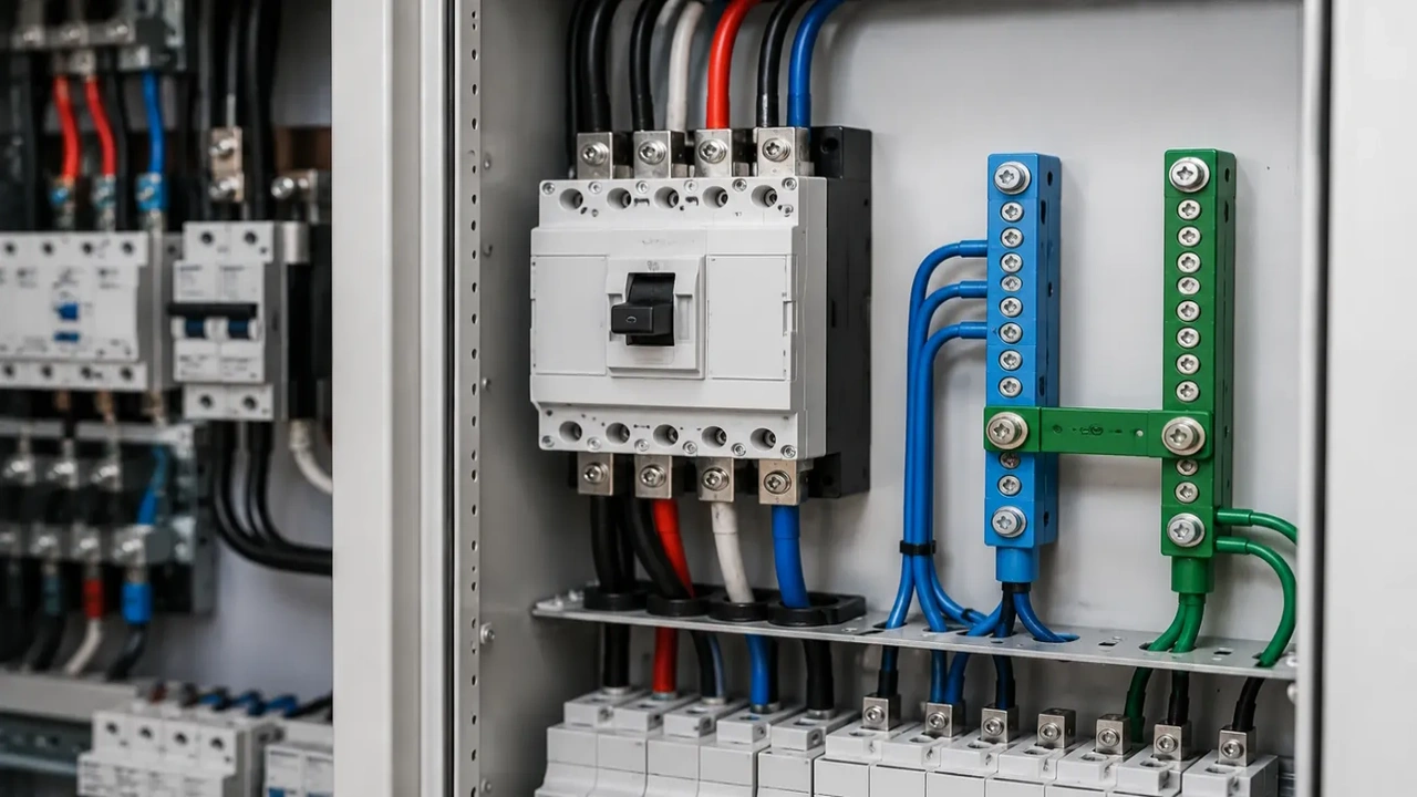
A tech pulls a panel schedule mid-troubleshoot and finds the neutral bar and the ground bar tied together with a green jumper screw, sitting on the same bus. First instinct: that looks like a short. It is not. This is the TN system, the grounding architecture behind almost every American service panel, and understanding why neutral and ground meet at one specific point is the difference between a five-minute fault trace and a half-day chase through the wrong circuit.
The TN system is not an optional design choice for most commercial and industrial buildings in the US. It is baked into how the utility delivers power and how the National Electrical Code requires the service to be bonded. Get the logic wrong and every downstream fault reading, every VFD nuisance trip tied to ground noise, and every PLC I/O card damaged by a stray potential becomes harder to explain.
What the TN System Actually Means
TN stands for Terre Neutre, French shorthand carried into international standards, meaning the neutral point of the supply transformer is earthed at the source, and exposed conductive parts of the installation connect to that same earthed neutral rather than to an independent ground rod system.
In plain shop terms: the utility transformer's neutral gets driven into the earth. Your building's ground system connects back to that same neutral reference instead of standing alone. Fault current on a TN system has a low-impedance metallic path home through neutral and bonding conductors, not through the dirt.
That low-impedance path is the entire point. A fault current trying to return through earth alone faces high resistance, which means low fault current, which means your breaker or fuse may never see enough current to trip.
TN topology forces fault current high enough, fast enough, to clear the breaker before someone gets hurt or equipment cooks.
The Three TN Variants (and Which One the US Uses)
International standards split TN into three subtypes based on how neutral and protective earth conductors run through the installation.
TN-S keeps neutral and protective earth as separate conductors for the entire run, from the source to the last outlet. Common in parts of Europe and in US installations fed from a separately derived system, like a step-down transformer inside a plant.
TN-C combines neutral and earth into a single conductor, called a PEN conductor, for the whole run. Rare as a complete topology in the US because combining functions past the service point is restricted by code.
TN-C-S is what most American commercial and industrial services actually run. The utility feeds in a combined neutral-earth conductor up to the service point. At the main service disconnect, that combined conductor splits into a separate neutral and a separate equipment grounding conductor, and from that point forward they stay separate, like TN-S.
Why Neutral and Ground Share a Potential at the Service
Here is the mechanism a lot of apprentices skip past. Neutral carries return current under normal load. Ground carries fault current only, and should carry zero current in a healthy system. If they are bonded at more than one point, some neutral current finds a parallel path through ground conductors, conduit, and equipment frames.
That parallel path is what creates the classic symptoms: a multimeter reading a few volts between a grounded enclosure and true earth, a VFD drive fault tied to ground loop noise, or a PLC chassis that stings when you touch it under load. The system is bonded correctly, once, and every other bond becomes a shortcut for stray current.
By bonding neutral and ground together at exactly one point, usually the main service disconnect or the first disconnecting means on the property, the code forces neutral current to stay on the neutral conductor everywhere else.
One system, one reference point, zero ambiguity about which conductor should be carrying current under normal operation.
The Main Bonding Jumper Explained
The main bonding jumper is the physical connection, usually a screw, strap, or short conductor, that ties the neutral bus to the equipment grounding bus inside the service equipment. NEC 250.24 and 250.28 cover sizing and placement requirements for this connection.
Downstream of that jumper, every subpanel must keep neutral and ground on separate, insulated buses. A subpanel with neutral and ground bonded again, a common finding in older tenant buildouts, creates exactly the parallel current path described above. This is one of the most frequent code violations found during panel retrofits and one of the easiest to miss on a quick visual inspection.
Separately derived systems, meaning any transformer that creates a new neutral point downstream of the service such as a 480V to 208V step-down feeding a machine center, need their own bonding jumper at that transformer. Skipping this step is a common miss on new equipment installs where the electrical contractor assumes the panel upstream already handles it.
Field Scenario: Chasing a Phantom Voltage Reading
A packaging line starts throwing intermittent ground fault trips on a VFD feeding a conveyor motor. The maintenance tech measures 4 volts between the drive's grounding lug and a nearby structural steel column that should read zero. First assumption is a failing VFD or a motor insulation problem, both expensive guesses involving line downtime and possibly a same-day parts order.
Before pulling the drive, the tech traces the subpanel feeding that line and finds a leftover bonding screw connecting neutral and ground inside a 208V distribution panel installed during a line expansion two years earlier. That panel was never supposed to be bonded again, since it fed from the main service, not from a separately derived transformer.
Removing the incorrect bond drops the phantom reading to near zero and the ground fault nuisance trips stop. Total cost: one hour of tracing and a five-dollar part.
The alternative path, replacing a VFD or motor on a hunch, would have cost a shift of downtime and a same-day expedite fee on a component that was never the problem.
What Changes Downstream of the Service
Once past the main bonding point, the rules flip. Every subpanel, motor control center, and separately derived transformer secondary keeps neutral and ground isolated, connected back to the single bonding point through the equipment grounding conductor alone.
This matters directly for control panel builds. PLC racks, HMI enclosures, and VFD cabinets should reference ground through the equipment grounding conductor, not through a neutral tap taken for convenience inside the panel. A 120V control transformer secondary inside a machine panel is a separately derived system in its own right if it is not solidly connected to the primary side neutral, and it needs its own bonding jumper at that transformer.
Communication networks add another layer. Shielded cable for industrial networking protocols like PROFINET or EtherNet/IP should ground the shield at one end only in most topologies, following the same single-reference-point logic that governs the neutral-ground bond at the service. Grounding both ends recreates the same parallel-path problem at a much smaller, noisier scale.
TN vs TT vs IT: A Practical Comparison
| System | Neutral-Ground Bond | Fault Current Path | Typical Use Case | Trip Risk |
|---|---|---|---|---|
| TN | Bonded at one point, source referenced | Low impedance, metallic | US commercial/industrial services | Low, if rules followed |
| TT | Not bonded, separate earth electrodes | High impedance, through earth | European rural/utility setups | Higher, needs RCD |
| IT | Isolated or high-impedance grounded | Very low on first fault | Mines, hospitals, process plants | Low, needs insulation monitoring |
TN dominates American industrial buildings because it clears faults fast using standard overcurrent devices without requiring the ground fault monitoring hardware that IT systems demand. TT and IT systems solve different problems, mainly continuity of service and shock protection in installations without a reliable low-impedance earth path, but they are the exception in US panel shops, not the rule.
Common Mistakes During Panel Builds and Retrofits
Double bonding at a subpanel is the most common single error, usually inherited from a previous tenant's electrical layout or a hasty expansion job. It shows up as ground current on conductors that should be dead quiet and it will not always trip anything, which is why it survives inspection for years.
Missing bonding jumpers on separately derived systems is the second most common issue, particularly on new machine installs where a control transformer or a step-down unit gets wired without anyone treating it as its own grounding source. This one tends to surface only after a fault event, when the protective device does not clear as fast as expected.
Undersized bonding jumpers, sized off an assumption rather than the actual service conductor size per NEC Table 250.66, show up during commissioning audits more than during day to day operation. They pass a visual check and fail a calculation check, which is exactly why cross-referencing the code table against the as-built conductor size matters before signing off a panel.
Sourcing and Verifying Bonding Hardware
Bonding jumpers, ground bus bars, and main bonding screws look interchangeable on a supplier catalog page but are not. Sizing depends on the service conductor, and using an undersized or counterfeit component defeats the entire fault-clearing strategy the TN system depends on.
Cross-reference datasheets against the actual manufacturer part number before ordering, especially for ground bus kits sold as generic replacements for panel brands like Square D, Eaton, or Siemens. Counterfeit or gray-market bonding hardware is a known risk category in industrial power distribution and switchgear procurement, and a failure here does not show up until a fault event, when it is too late to catch on a supplier invoice.
Lead time also matters more than it looks on paper. A missing or damaged bonding jumper found during a shutdown window is not a part you want backordered. Sourcing through an authorized distributor with verified stock on standard panel components avoids a scheduled maintenance window turning into an unscheduled one.
Reliability, Maintenance, and Fault Clearing
A correctly bonded TN system is a predictive maintenance asset, not just a code checkbox. Stray neutral-ground current from an incorrect bond is measurable well before it causes a trip, which makes it one of the easier early warning signs available on a panel inspection.
Insulation resistance testing and neutral-to-ground voltage checks during scheduled PM rounds catch double-bonding faults long before they cause downtime. Building this check into a standard PM checklist costs a few minutes per panel and avoids the kind of unplanned VFD or PLC troubleshooting call described earlier in this article.
MTBF numbers on drives and control equipment assume a clean ground reference. A noisy ground path from a bonding error will not always kill a component outright, but it accelerates nuisance faults, shortens component life on sensitive electronics, and quietly increases the real cost of ownership on equipment that was speced correctly in the first place.
Talk to Techno Control Corp
If a panel is throwing ground fault codes that do not match an obvious mechanical or electrical failure, the bonding scheme is worth checking before any part gets replaced. Techno Control Corp sources verified panel components, bonding hardware, PLCs, and VFDs from authorized distributors, and our team can help trace a grounding issue or spec a control panel build that gets the bonding right the first time. Reach out to our sourcing team with your panel schedule and we will help you work through it.
Related products
Components from our catalogue relevant to this article — request a quote for availability, lead time and pricing.
/TC625 AF100 ABB - Coaxial Modem 3BSE002224R1.png "ABB TC625 AF100 ABB - Coaxial Modem 3BSE002224R1 | Coaxial modem TC625 AF100")
TC625 AF100 ABB - Coaxial Modem 3BSE002224R1
Coaxial modem TC625 AF100
/SB512 ABB - Power Supply 3BSE002098R1.png "ABB SB512 ABB - Power Supply 3BSE002098R1 | SB512 power supply module")
SB512 ABB - Power Supply 3BSE002098R1
SB512 power supply module
/DSSS 171 ABB - Voting Unit 3BSE005003R1.png "ABB DSSS 171 ABB - Voting Unit 3BSE005003R1 | DSSS 171 voting unit for safety systems")
DSSS 171 ABB - Voting Unit 3BSE005003R1
DSSS 171 voting unit for safety systems
/4NWP100174R0001 ABB - UPS PowerValue 11LI Up 2000 VA.webp "ABB 4NWP100174R0001 ABB - UPS PowerValue 11LI Up 2000 VA | UPS PowerValue 11LI Up 2000 VA")
4NWP100174R0001 ABB - UPS PowerValue 11LI Up 2000 VA
UPS PowerValue 11LI Up 2000 VA