
Solid State Relays: Sizing, Heat, and the Failure Modes Nobody Plans For

Quick Answer
A solid state relay dissipates real heat under every amp it carries, and skipping the heat sink calculation is the top reason panels run hot and relays fail shorted. Here's how to size one, protect it with the right fuse, and know when a contactor is still the smarter choice.
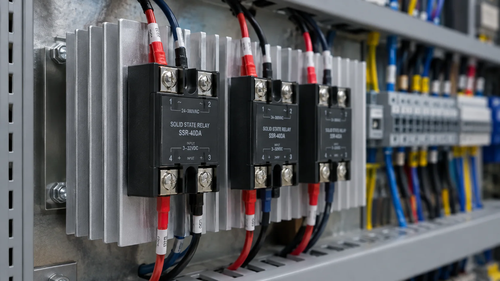
A solid state relay doesn't look like a heat problem. There's no coil, no moving contact, nothing that sparks or wears with each cycle. Mount one next to an electromechanical contactor doing the same job, and it's the solid state relay, not the contactor, that needs a heat sink and a place in the enclosure's thermal budget. Get that wrong and the relay doesn't just run warm: it runs hot enough to shorten its own life, and when it finally lets go, it fails in the direction that leaves the load still energized.
That's the real story with a solid state relay: fast switching and millions of cycles are genuinely useful, but none of it matters if the heat at rated current was never calculated. This piece covers the solid state relay heat sink calculation itself, the derating and surge rules built on it, the failure mode that makes series protection non-negotiable, and where a solid state relay is the wrong tool.
A solid state relay doesn't switch a load so much as it becomes part of that load's heat problem for as long as it stays closed.
What Is a Solid State Relay?
A solid state relay is a switching device that turns an electrical load on and off with a semiconductor output stage instead of a mechanical contact. On the control side, a low-voltage DC signal, commonly 3 to 32 VDC, drives an LED inside an optocoupler, isolated from the load side by a few kV. On the load side, the switching element is a triac for smaller AC loads, back-to-back thyristors for higher-current AC loads, or a power MOSFET or IGBT for DC duties. There's no coil, no armature, no contact bounce, and no arc.
That construction is why a solid state relay switches in well under a millisecond, tolerates millions of operations, and runs silently, which is why plants pair them with PID-driven temperature control loops and high-frequency heater control. It's also why the rest of this piece is about heat: a semiconductor junction carrying current isn't a near-zero-resistance path the way a closed contact is, and that difference in physics is the whole story.
Where the Heat Actually Comes From
Here's the part of solid state relay sizing skipped most often: the output device has a forward voltage drop even when fully on. For a triac or SCR-based AC solid state relay, that drop typically runs 1.0 to 1.6 V, staying close to flat across the relay's rated current range. Multiply that voltage by the load current and you have the power the relay dissipates as heat, continuously, for as long as it conducts: P = V(on) × I(load).
Run the numbers on a 40 A load at a representative 1.5 V drop and you get 60 W dissipated inside the relay every second it's on. Celduc, a major European SSR manufacturer, uses almost the identical example in its own thermal design guidance: a relay conducting 40 A at around 1.6 V dissipates more than 60 W continuously. That's why the same 40 A load a contactor's closed contact carries with a few watts of resistive loss becomes a 40 to 60 W heat source once a solid state relay switches it instead, and why a contactor needs no heat sink calculation while an SSR in the same duty almost always does.
How Do You Size a Solid State Relay Heat Sink?
You size a solid state relay heat sink by working backward from a temperature budget: take the maximum case temperature the datasheet allows, subtract the worst-case ambient the relay will actually see, and divide what's left by the power dissipated at full load. What's left is the total thermal resistance, in °C per watt, the heat sink has to close, a calculation our electrical engineering team runs on any panel carrying continuous-duty SSRs.
That path has more links than most first-pass specs assume: junction to case, a fixed datasheet figure commonly 0.4 to 0.9 °C/W for panel-mount 40 to 50 A units, consistent with published thermal specs across panel-mount SSR lines from manufacturers like Crydom and Littelfuse; case to heat sink across the mounting interface, where skipped thermal grease can double it; and heat sink to ambient, the number you're solving for. "Ambient" means the air around the relay inside a running panel, not room temperature on the drawing: a cabinet with drives, transformers, and other SSRs commonly runs 10 to 15°C hotter inside than the room around it, a gap sizing against room temperature alone misses.
Work the numbers: a 40 A heater load at a 1.5 V drop is 60 W to dissipate. Target a case temperature 20°C below datasheet maximum, the margin Celduc itself recommends for long-term reliability, against a worst-case cabinet ambient of 50°C rather than a 40°C reference. That's an 80°C target against 50°C ambient: allowable resistance from case to ambient is 30°C ÷ 60 W = 0.5°C/W. Subtract roughly 0.15°C/W for a properly greased interface, and the heat sink itself needs to hold 0.35°C/W or better under real convection, not a manufacturer's open-bench figure.
Derating the Nameplate: 2x for Resistive Loads, Up to 7x for Inductive Loads
That's why panel builders rarely size a solid state relay at its literal nameplate current for the actual load. Sizing guidance from SSR manufacturers like Celduc, Eurotherm, and Omron converges on a derating factor, not a flat multiplier: roughly 2x to 2.5x the expected continuous current for a benign resistive load in a ventilated panel, and 5x to 7x for an inductive or capacitive load, where switching transients push real stress above the steady-state reading. A tightly packed enclosure or high-ambient site pushes toward the top of either range. Nameplate current is a laboratory number, with no allowance for real cabinet temperature or mounting losses. Skipping the actual solid state relay heat sink calculation is how a relay rated for the job on paper still fails early in the field.
Surge Ratings for Heater and Transformer Loads
Continuous current rating and surge current rating are two different numbers on an SSR datasheet, and sizing a relay against only the first is a common, expensive mistake on two ordinary load types: resistive heaters and transformers.
A cold heating element, a quartz or tungsten infrared emitter especially, has a cold resistance that can run a tenth of its hot, operating resistance, so full voltage on a cold element draws a momentary inrush many times steady-state current, decaying within a handful of cycles. A transformer primary behaves similarly for a different reason: magnetizing inrush from core saturation and residual flux commonly runs 8 to 12 times rated current on the first half-cycle per IEEE 141-1993, climbing toward 20 times on small transformers, depending on where in the waveform the switch closes.
The datasheet number that matters here is the one-cycle, non-repetitive surge rating, sometimes listed as I(TSM), not the continuous rating used for the heat sink calculation. A relay correctly sized on continuous current and heat can still fail on the first energization of a cold transformer or heater bank. For transformer switching, TE Connectivity's and OMRON's application notes on switching transformer loads with solid state relays recommend selecting a relay with a half-cycle surge rating greater than the peak line voltage divided by the transformer's primary winding resistance.
Zero Cross vs Random Turn-On vs Phase-Angle Control
How a solid state relay actually switches the load, not just when commanded to, is a load-type decision as much as a control decision, and manufacturers build three distinct switching behaviors into their product lines for exactly that reason.
Zero Cross Control for Resistive Loads
A zero cross solid state relay waits for the AC waveform to cross zero volts before closing, then holds the load on for a whole number of half-cycles. Switching at the zero point avoids the current step and electrical noise a mid-cycle closure creates, which is why zero-cross switching is the default for resistive heating: heater banks, immersion heaters, and any load a PID loop cycles many times a minute through burst firing. A zero cross solid state relay on a resistive load is close to a free improvement in noise and relay stress.
Random Turn-On for Inductive Loads
A random, or instant-on, solid state relay closes the instant the control signal arrives, regardless of where the AC waveform sits. That's the right behavior for inductive loads: small motors, solenoid valves, contactor coils, and transformers, where fast, deterministic response matters more than waveform timing, and it's the building block every phase-angle relay is built on.
Phase-Angle Control for Continuously Variable Power
Phase-angle, or phase-fired, control fires the output device at a continuously variable point within each half-cycle instead of only at the zero crossing, delivering true proportional power rather than an on/off average. It suits infrared heating zones needing fine power trim and lighting dimming, but it costs more: firing mid-waveform creates a faster voltage step, with more electrical noise and dv/dt stress than zero-cross or random turn-on produce, similar in spirit to the reflected-wave stress a VFD's inverter output puts on a motor.
Why Do Solid State Relays Fail Shorted?
Solid state relay failure modes split into two broad categories, but one dominates: solid state relays predominantly fail shorted, not open, because the semiconductor junction punches through into a permanently conductive state under thermal or current overstress, rather than opening the way a fuse element does. Sustained overcurrent, a degraded heat sink connection, blocked airflow, or a surge beyond the device's I²t rating are the usual paths there, tracing back to the heat and surge numbers above.
The consequence is what makes this genuinely dangerous, not just inconvenient: the load stays energized with the control signal already withdrawn. A heater bank that won't turn off, a solenoid that won't de-energize, or a motor that keeps running after the PLC commands a stop is the documented, predominant failure behavior, with no sign of failure until something downstream notices the load is still live.
That's why a solid state relay is never the only device between a load and the supply on anything that matters. Two things belong in series with it: a fast semiconductor fuse, rated to IEC 60269-4's aR class or UL 248-13 in North America, sized so its clearing I²t sits below the relay's I²t-for-fusing rating, since a standard fuse protects the wire, not a thyristor junction failing in microseconds; and a mechanical isolating device, a contactor or rated disconnect, giving a true, visible air gap a hard-wired safety function can open independent of the SSR. Protection coordination and preventive maintenance has to assume the semiconductor will eventually fail in its worst mode, not its best.
A solid state relay that fails doesn't fail open and go quiet. It fails shorted, with the load still live and the command to stop already ignored.
Leakage Current and Snubbers: The Off State Isn't Fully Off
The shorted failure above is the most consequential of the solid state relay failure modes, but two more are worth planning for before they show up in the field.
Off-State Leakage Current
An open solid state relay isn't a true open circuit. The output device still passes a small off-state leakage current, commonly a few mA up to around 10 mA, because a semiconductor junction never reaches the near-infinite resistance of an open mechanical contact. On a load drawing meaningful current, that leakage is irrelevant; on a small load, an indicator lamp or a small relay coil, it can keep the load faintly energized: a pilot light that never fully darkens, or a coil that hums or stays lightly picked up. The standard fix is a bleeder resistor across the load, giving that leakage a path that bypasses it.
Snubbers and dv/dt
Switching off an inductive load creates a rapid voltage rise across the now-open relay, and if that rate of rise, dv/dt, exceeds the output device's rating, it can retrigger the triac or thyristor into conduction with no control signal present: a false turn-on caused entirely by the load. An RC snubber network across the output absorbs that transient and keeps dv/dt inside rating, standard practice on any solid state relay switching a motor, solenoid, or transformer.
The tradeoff is real: a snubber adds its own leakage current on top of the relay's native leakage, which can turn a marginal small-load leakage problem into an actual one. Some manufacturers offer snubberless output devices, rated for high enough dv/dt that the network isn't needed, worth requesting on a leakage-sensitive load, the same transient-management problem covered more broadly in our guide to industrial surge protection.
Three Phase Solid State Relay Configurations
A three phase solid state relay assembly is usually built one of two ways: three independent single-pole SSRs, one per phase, mounted on a common heat sink, or a single integrated three-phase module in one housing. The independent-leg approach suits field-repairable panel builds, since a failed leg can be swapped without disturbing the other two.
How many legs need switching depends on the load's connection. A delta-connected load, or a wye load with no neutral present, only needs two of three legs switched, since opening any two de-energizes the whole circuit; a wye load with a neutral present needs all three legs controlled, since current can otherwise still flow through the neutral. Zero-cross firing across the three legs should also be synchronized on a balanced heater bank, since firing each leg independently can imbalance the current the three phases draw from upstream protection.
The heat budget scales directly with leg count: three 40 A legs dissipating roughly 60 W each is close to 180 W in one section, not 60 W, exactly the kind of change that needs the panel's cooling design revisited, not just three more relays bolted onto the existing heat sink.
A Real-World Scenario: The Barrel Heater That Wouldn't Turn Off
The Setup
A plastics extrusion plant ran six barrel heater zones on one extruder line, each a resistive band heater controlled by a zero cross solid state relay under closed-loop PID control, cycling on and off dozens of times an hour. Each zone's SSR sat on a shared heat sink strip, protected only by the same thermal-magnetic breaker sized for the wire gauge, with no series contactor, on the reasoning that the SSR was already the switching device.
What Went Wrong
Two zones were added during a later die upgrade, and two more relays went onto the same heat sink strip without rerunning the panel's heat budget. Cabinet-internal temperature crept up over the following months, unmeasured. One relay, running hotter than its datasheet assumed, eventually failed shorted. The breaker, sized correctly for the wiring, saw a normal load current, since the heater element wasn't faulted; there was no overcurrent event to react to, only a control device stuck closed. The PID issued its off command on schedule, and the zone stayed at full power until an operator caught the melt-temperature alarm.
The Fix
The retrofit added three things: a fast semiconductor fuse in series with every zone's SSR, sized to the relay's I²t rating rather than the wire's ampacity; a motor-rated isolating contactor ahead of each zone, wired through a hard-wired over-temperature limit switch independent of the SSR or controller logic; and a heat sink and ventilation recalculation for the panel that actually existed, not the one on the original drawing. It's the panel-heat-budget review our industrial automation team builds into any retrofit that adds load.
The SSR did exactly what a failed solid state relay does. Nothing downstream of it had been designed to assume that it eventually would.
Solid State Relay vs Mechanical Relay: What Actually Changes
The solid state relay vs mechanical relay question comes up on nearly every panel design, and it's worth a labeling note first: some manufacturers market the same heat-sink-equipped device as a solid state contactor rather than a solid state relay, generally at higher current ratings for sustained duty. The two terms describe identical technology, and a solid state contactor still needs the same heat sink calculation and series fuse as any other solid state relay.
| Characteristic | Solid State Relay | Electromechanical Contactor/Relay |
|---|---|---|
| Switching mechanism/speed | Semiconductor junction (triac, SCR, IGBT, MOSFET); sub-millisecond, silent, no arc | Mechanical contacts and coil; tens of milliseconds, audible, contact arcing |
| Typical life | Millions of cycles; MTBF often exceeds 7 million hours | 50,000-200,000 operations at rated load; a manufacturer rating tested under IEC 60947-4-1 categories, not a standard-specified figure |
| On-state loss | Continuous, roughly 1-1.5 W per amp of load current | Near zero; a few watts from contact resistance |
| Off-state isolation | Leakage current typically a few mA; not a true open circuit | True mechanical air gap, suitable for lockout/tagout |
| Predominant failure mode | Shorted, load remains energized | Open; contacts eventually fail to close reliably |
| Overcurrent protection | Semiconductor fast fuse coordinated to device I²t | Standard branch-circuit fuse or MCB |
| Best fit | High-frequency/burst-fire cycling, proportional control | Infrequent switching, visible isolation |
When Should You Use an SSR Instead of a Contactor?
Use a solid state relay instead of a contactor when the load cycles often enough that contact wear becomes the limiting factor: burst-fire heater control switching dozens of times an hour, or any duty where silent, arc-free switching genuinely matters. Stick with a contactor when cycling is infrequent, or the circuit needs a visible open point for lockout/tagout. Neither device is universally correct: an SSR bought reflexively for a load that starts once a shift buys heat, cost, and shorted-failure risk for switching speed the application never needed.
None of this argues against using solid state relays. It argues for treating the heat sink calculation, the surge rating, and the series fuse as part of the specification, not an afterthought bolted on after a relay fails in the field. Our engineering team runs that exercise on panel builds carrying heater zones and other frequent-cycling loads, sourcing the relays, semiconductor fuses, and contactors to match through our products catalog once the numbers are settled.
Frequently Asked Questions
What is a solid state relay?
A solid state relay switches a load on and off using a semiconductor output stage, a triac, thyristor pair, MOSFET or IGBT, instead of a mechanical contact, isolated from the control signal by an optocoupler. It switches in under a millisecond and survives millions of cycles, but the semiconductor junction carrying the load current generates real heat a mechanical contact never does.
How do you size a solid state relay heat sink?
Work backward from a temperature budget: take the relay's maximum allowed case temperature, subtract the worst-case ambient it will actually see inside a running panel, and divide the remainder by the power dissipated at full load to get the thermal resistance, in °C per watt, the heat sink has to close.
Why do solid state relays fail shorted?
The semiconductor junction punches through into a permanently conductive state under thermal or current overstress rather than opening like a fuse element. That means the load stays energised even after the control signal is withdrawn, which is why a fast semiconductor fuse and a separate mechanical isolator always belong in series with an SSR on anything that matters.
When should you use an SSR instead of a contactor?
Use a solid state relay when the load cycles often enough that contact wear on a mechanical device would become the limiting factor, such as burst-fire heater control switching dozens of times an hour. Stick with a contactor for infrequent cycling or where the circuit needs a visible, lockable open point.
Related products
Components from our catalogue relevant to this article — request a quote for availability, lead time and pricing.
/RP1A23D5.webp "Carlo Gavazzi RP1A23D5 Carlo Gavazzi - PCB Mount Solid State Relay 5 A 230 VAC | PCB mount AC solid state relay, zero cross, 5 AACrms, 230 VACrms")
RP1A23D5 Carlo Gavazzi - PCB Mount Solid State Relay 5 A 230 VAC
PCB mount AC solid state relay, zero cross, 5 AACrms, 230 VACrms
/RGC3A60D20KKE.webp "Carlo Gavazzi RGC3A60D20KKE Carlo Gavazzi - 3-Phase Solid State Relay 20 A with Integrated Heatsink | 3-pole solid state contactor, 20 A per pole, 42 to 660 VAC, integrated heatsink")
RGC3A60D20KKE Carlo Gavazzi - 3-Phase Solid State Relay 20 A with Integrated Heatsink
3-pole solid state contactor, 20 A per pole, 42 to 660 VAC, integrated heatsink
/RGC1A60D30KKE.webp "Carlo Gavazzi RGC1A60D30KKE Carlo Gavazzi - 1-Phase Solid State Contactor 30 A DC Control | 1-pole solid state contactor, 30 AAC, 42 to 660 VAC, DC control")
RGC1A60D30KKE Carlo Gavazzi - 1-Phase Solid State Contactor 30 A DC Control
1-pole solid state contactor, 30 AAC, 42 to 660 VAC, DC control
/RGC1A60A25KKE.webp "Carlo Gavazzi RGC1A60A25KKE Carlo Gavazzi - 1-Phase Solid State Contactor 25 A AC Control | 1-pole solid state contactor, 25 AAC, 42 to 660 VAC, 17.5 mm wide")
RGC1A60A25KKE Carlo Gavazzi - 1-Phase Solid State Contactor 25 A AC Control
1-pole solid state contactor, 25 AAC, 42 to 660 VAC, 17.5 mm wide