
Industrial Surge Protection: Stopping Voltage Transients Before They Destroy Machinery

Quick Answer
Industrial surge protection works by staging Type 1, Type 2, and Type 3 surge protective devices, per IEC 61643-11 and UL 1449, from the service entrance down to VFDs and PLCs, and it only keeps working long-term if the grounding behind it is verified and every device gets checked for silent MOV degradation before it fails.
A voltage transient lasts microseconds. The IGBT module it destroys costs a production shift to replace and weeks to re-source. That mismatch, milliseconds of cause against days of consequence, is why industrial surge protection gets treated as an afterthought until the first VFD input bridge fails on a plant that had no idea it was exposed. Surges don't announce themselves. They ride the same conductors carrying normal load current, do their damage in a fraction of a cycle, and leave a fault code that rarely points back to the actual cause. Power surge damage to machinery gets logged as a random component failure far more often than it gets traced to the transient that caused it.
This piece covers what generates damaging transients in a plant, how staged surge protective device (SPD) selection works under IEC 61643-11 and UL 1449, why the clamping voltage on a datasheet means less than assumed, and why an SPD installed correctly on day one can be doing nothing by year three.
What Actually Causes Industrial Voltage Surges
Plant electricians tend to blame lightning for every transient event. It's a real threat, but rarely the dominant one inside a facility running its own motors, drives, and switching equipment.
Lightning-Induced Transients
A direct or nearby lightning strike, even one hitting a transmission line miles away, injects a massive current impulse into the utility distribution system or the facility's own grounding network, and that impulse propagates down the service conductors as an induced transient. These events are rare compared to internal switching transients, but they carry the highest energy content of any surge type, which is why standards treat lightning-class events as a distinct category with its own test waveform, covered below.
Utility Switching Transients
Utilities switch capacitor banks on their distribution feeders to manage voltage profile and power factor, and that switching action launches an oscillatory transient onto the line. Feeder reclosing and transformer tap changes produce similar disturbances. None of this is a malfunction, but it still arrives at your service entrance as a voltage transient.
Internal Switching of Large Inductive Loads
This is the source most facilities underestimate. Every time a large motor starts across the line, a contactor opens under load, a transformer energizes, or a capacitor bank switches in, the collapsing magnetic field generates a voltage spike that propagates through the plant's own distribution system. A shorted motor winding tripping offline, a welder striking an arc, a VFD's own output switching: these events never pass through a utility-side SPD, because they originate downstream of it. Electrical surge protection for factories that only addresses the incoming service and ignores internally generated transients is protecting against the wrong half of the threat.
Transient Energy and Duration: Why Not All Surges Are Equal
A surge is defined by more than peak voltage. Energy content and duration determine what it actually does to downstream equipment, and the industry standards reflect that with distinct test waveforms rather than a single number.
IEEE C62.41 established the location category framework still referenced industry-wide: Category C for outside and service-entrance locations, Category B for distribution panels and short branch circuits, and Category A for outlets and branch circuits more than about 10 meters (30 feet) from a Category B panel. A lightning-class event at Category C uses a 10/350 microsecond waveform: current rises to peak in 10 microseconds and decays to half-peak in 350 microseconds. That long tail carries far more energy than a switching transient at a comparable peak voltage, which is why Type 1 SPDs are physically larger and built around spark gap or hybrid technology rather than a MOV alone.
Switching transients, whether utility capacitor bank operation or internal motor and contactor switching, are represented by the 8/20 microsecond combination wave: fast rise, fast decay, lower total energy than a lightning waveform even at a comparable peak voltage. This is the waveform used to test Type 2 and Type 3 devices. The practical takeaway for anyone specifying protection: a device rated correctly for combination-wave switching transients is not automatically rated for lightning current, and vice versa. Matching the SPD's test waveform to the actual threat at that point in the system is not optional.
SPD Types and Staged, Coordinated Protection
Modern industrial facilities don't lean on a single transient voltage surge suppressor, the older term for what current standards simply call an SPD, doing all the work at one point in the system. A device mounted only at the service entrance cannot address a transient generated three panels downstream by a capacitor bank or a VFD. Coordinated, multi-stage protection is the accepted approach under both IEC 61643-11 and UL 1449, mapped onto three device types. Techno Control Corp stocks Type 1, Type 2, and Type 3 devices from established manufacturers through our products line, sized to the application rather than sold as a generic part.
Type 1: Service Entrance Protection
Type 1 SPDs are rated to handle partial lightning current and are installed ahead of or immediately at the main service disconnect, on either the line or load side. Under IEC 61643-11 these are tested with the 10/350 microsecond waveform and rated by Iimp, the impulse current they can survive. Under UL 1449 5th edition (2021), permanently connected Type 1 devices serve the same role. NEC 230.67 first mandated a Type 1 or Type 2 SPD at the service equipment for dwelling units starting with the 2020 NEC, and the 2023 cycle expanded that requirement to cover services and feeders for dormitories, hotel and motel guest rooms, and nursing home and limited-care facility patient sleeping rooms, a sign code bodies keep widening where this first stage is mandatory.
Type 2: Distribution and Sub-Panel Protection
Type 2 SPDs sit at distribution boards, motor control centers, and sub-panels feeding VFDs, PLCs, and process equipment. They're rated by nominal discharge current (In) and maximum discharge current (Imax) using the 8/20 microsecond combination wave rather than the lightning waveform. This is the workhorse tier for most industrial facilities: a Type 2 device at every MCC and control panel feed catches both the residual energy that passes the Type 1 device and the transients generated internally by switching within the plant that never touch the service entrance.
Type 3: Point-of-Use Protection for Sensitive Equipment
Type 3 SPDs are installed at or very near the equipment being protected, with UL 1449 specifying a minimum conductor length (commonly 10 meters, 30 feet) between the upstream Type 2 device and the Type 3 unit so the two stages actually coordinate rather than the downstream device seeing no useful voltage difference to clamp against. Type 3 devices carry the lowest clamping voltage of the three tiers and the lowest current-handling capacity, the correct tradeoff since most of a transient's energy should already be diverted upstream by then.
Staged protection isn't redundancy. Each stage is doing a job the others structurally cannot do, and skipping a stage leaves a gap no downstream device can close.
Clamping Voltage and Let-Through Voltage: Reading the Number Correctly
The clamping voltage, sometimes called the let-through voltage or Voltage Protection Level (Up) under IEC terminology, is the peak voltage that reaches the protected equipment during a defined test surge. Every transient voltage surge suppressor on the market publishes this number, and it's the figure most often read wrong. It is not a hard ceiling. It's a measured value at a specific test current and waveform, and a larger surge than the test condition produces a higher let-through voltage than the datasheet number.
This matters when comparing devices. A lower clamping voltage rating isn't automatically the better choice for every location; it typically also means a lower energy-handling capacity, which is why the lowest clamping voltage devices belong closest to sensitive electronics (Type 3) rather than at the service entrance, where the device has to survive a much larger event first. Sizing an SPD purely on the lowest advertised clamping voltage number, without checking its discharge current rating against actual duty, is a common and expensive specification mistake.
Lead length compounds this. Every SPD has connecting leads between the bus and the protected conductor, and inductance in those leads adds its own voltage rise during a transient's fast rise time, stacking on top of the device's own clamping performance. A Type 3 device with excellent datasheet numbers, installed with long coiled leads to fit a crowded panel, delivers worse real-world let-through voltage than the same device wired short and straight. It's one of the most common mistakes on retrofit installations where the SPD gets added after the panel was already built.
Why Grounding and Bonding Determine Whether an SPD Actually Works
An SPD doesn't stop a transient from happening; it gives the current a lower-impedance path than the load, clamping the voltage between line and ground by shunting current to the grounding system. That only works if the grounding path is low-impedance and the bonding between the SPD's ground reference and the equipment it's protecting is solid. An SPD connected to a corroded ground rod, a loose bonding jumper, or a grounding electrode system with unverified continuity is not providing the protection its datasheet promises, no matter how good the device is.
This is the same principle covered in our piece on why neutral and ground meet at exactly one point in a TN system: a protective device's effectiveness depends on the bonding architecture behind it, not just the rating on the device. It's why industrial surge protection audits start with a ground resistance check, not a device inventory. A high-quality SPD on a poorly bonded panel still lets a transient reach the load, because the voltage it's supposed to clamp shows up as a difference between two ground references that were never at the same potential during the event. Ground resistance and bonding jumper checks have to happen at commissioning and repeat on an interval, not get assumed because the panel passed inspection once.
Where to Install SPDs Relative to VFDs, PLCs, and Sensitive Electronics
Effective industrial surge protection depends on placement as much as device selection. Placement isn't just about proximity, it's about which side of a filter, isolation transformer, or line reactor the device sits on, and what specifically it's defending.
A Type 2 SPD at the MCC feeding a VFD lineup protects the drive's input rectifier and DC bus from transients arriving on the incoming feeder, including transients generated by other equipment on the same bus, like a neighboring motor starting or a capacitor bank switching. It does not protect the drive's output side, where the VFD's own switching generates high-frequency voltage spikes that require different mitigation (output reactors, dV/dt filters), a separate problem from the transient protection covered here.
PLCs and their I/O modules are typically the most surge-sensitive components in a panel, because their circuits interface directly with field wiring and long cable runs that pick up induced transients even without a direct power connection. A Type 3 SPD at the PLC's power supply input, plus surge protection on critical I/O runs leaving the panel, closes a gap Type 2 protection alone doesn't address. Facilities relying on a UPS for control system ride-through should treat that as a separate layer; a UPS addresses outages and sag, not fast transients, a distinction covered in how to choose the right UPS for industrial control systems.
The practical rule: every meaningful drop in the distribution hierarchy where sensitive electronics connect deserves its own coordinated SPD stage, not a single device upstream expected to catch everything.
SPD Type, Location, and Clamping Behavior at a Glance
| SPD Type | Typical Location | Test Waveform | Primarily Protects | Typical Clamping Behavior |
|---|---|---|---|---|
| Type 1 | Service entrance, main switchboard, line or load side of main disconnect | 10/350 μs (Iimp rating) | Entire facility from lightning current and major utility-side events | Higher let-through voltage; sized to survive high energy, not to give the lowest clamp |
| Type 2 | Distribution panels, MCCs, sub-panels feeding VFDs and process equipment | 8/20 μs combination wave (In/Imax rating) | Feeders, motor control buckets, drive input sections | Moderate clamping voltage; workhorse stage catching both residual and internally generated transients |
| Type 3 | Point of use, at or within a few meters of the protected device | 8/20 μs combination wave, lower current rating | PLCs, HMIs, instrumentation, sensitive I/O | Lowest clamping voltage of the three tiers; low energy handling, must be coordinated with an upstream Type 2 |
SPD End-of-Life: Why "Installed Once, Forgotten Forever" Is a Real Failure Mode
Most industrial SPDs use MOVs (metal oxide varistors) as the primary clamping element. Every surge the MOV absorbs causes a small, permanent shift in its ceramic structure, raising leakage current and lowering the voltage at which it starts conducting. That's normal, expected wear, not a defect, but it's invisible from outside the enclosure. A MOV can absorb dozens of moderate transients over several years and still look physically intact while its protection margin has quietly collapsed. Left unchecked, a degraded MOV eventually reaches thermal runaway: it conducts continuously at line voltage, heats up, and the heat lowers its resistance further until it fails, ideally through a built-in thermal disconnect, or worse, by cooking the busbar it's connected to.
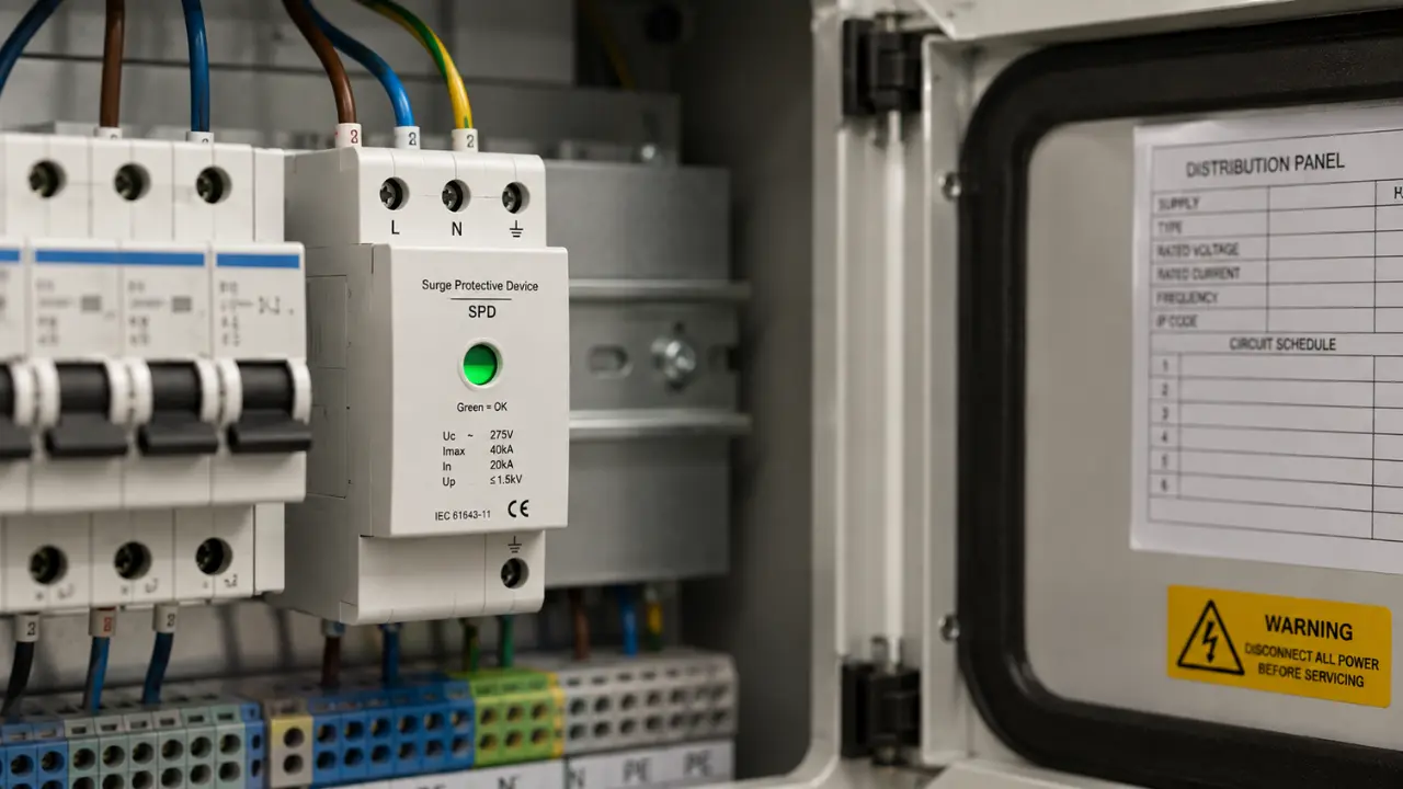
Quality SPDs include a visual status indicator, often a window that changes from green to red when the thermal disconnect has activated, and many industrial-grade units also provide a dry contact for remote monitoring through the PLC or SCADA system. That contact is worth wiring back to the control system on every panel where it's available. An SPD that failed silently six months ago provides zero protection today while giving every appearance, to anyone who doesn't check the indicator, of doing its job.
This is the failure mode plants run into constantly: an SPD gets specified and installed correctly at commissioning, nobody puts it on a maintenance checklist, and years later it has absorbed enough surge duty that its clamping performance is a fraction of the nameplate rating. Power surge damage to machinery that shows up years into a plant's operating life is almost always traced back to this kind of silent degradation, not a missing device. The next significant switching event goes straight through to the equipment it was supposed to protect. Folding SPD indicator checks and periodic leakage current testing into a facility's electrical maintenance and reliability program closes that gap, and it's the single highest-leverage thing a maintenance team can do to keep a surge protection device program functional for years.
A Real-World Scenario: The VFD That Had "Protection" That Wasn't Protecting Anything
A mid-sized manufacturing plant running a bank of extruder line VFDs off a shared MCC bus had Type 2 SPDs installed on the MCC at commissioning, three years prior. On paper the installation was correct: SPDs feeding sensitive drive electronics, sized to the bus rating.
During a routine facility upgrade, a new power factor correction capacitor bank was energized on the same bus. The switching transient propagated through the MCC bus. One VFD tripped on an instantaneous overvoltage fault and, on inspection, showed a failed input rectifier bridge and visible damage on the IGBT gate driver board, consistent with a fast transient exceeding the drive's internal protection threshold.
The SPD at that MCC section had, in fact, been doing its job for three years, absorbing routine switching transients from motor starts and contactor operations on the bus. Nobody had checked its status indicator since commissioning. When it was pulled and inspected, the indicator window showed red: the thermal disconnect had already activated, most likely from cumulative MOV degradation, and the device had been inert in the panel for an unknown period before the capacitor bank event that finally found the unprotected drive behind it.
The SPD wasn't wrong when it was specified. It was wrong three years later, when nobody checked whether it was still a surge protection device or just a device that used to be one.
The fix was straightforward: replace the failed SPD, wire its status contact into the PLC for remote alarm, and add SPD indicator checks to the plant's quarterly maintenance rounds. Because the same switching event stressed every motor on that bus, not just the drive that tripped, the plant also scheduled insulation resistance and surge testing across the rest of the extruder motors, the kind of diagnostic work covered in motor testing methods and what each test actually catches before failure, since transient-induced winding stress doesn't always announce itself as an immediate trip. The costlier lesson was the unplanned VFD repair and that a routine, planned capacitor bank energization exposed a protection gap that had existed silently for months.
Getting the Specification and the Maintenance Right
Industrial surge protection is not a single device purchase, it's a system: a Type 1 stage sized for the facility's lightning and utility exposure, Type 2 stages at every panel feeding motor control equipment, Type 3 protection tight to PLCs, grounding verified rather than assumed, and a maintenance program that checks whether each stage is still functioning rather than trusting the installation date. Skip any piece and the rest of the system is protecting against a threat that isn't the one that eventually shows up.
If you're specifying electrical surge protection for factories with sensitive drive and PLC loads, or trying to figure out why a facility keeps losing drives or PLC I/O cards after switching events, our engineering team can walk your one-lines, confirm SPD coordination and grounding integrity, and source the right devices from verified manufacturers. Our audits and power system optimization service is built for exactly this kind of diagnostic work. Contact us to talk through your panel layout and get a protection scheme that still works in year five, not just at commissioning.
Related products
Components from our catalogue relevant to this article — request a quote for availability, lead time and pricing.
/GHB3030-GR1 Eaton.webp "Eaton GHB3030-GR1 Eaton | Eaton GHB Circuit Breaker")
GHB3030-GR1 Eaton
Eaton GHB Circuit Breaker
/009737 Eaton - ZW7-240.webp "Eaton 009737 Eaton - ZW7-240 | Eaton Overload Relay")
009737 Eaton - ZW7-240
Eaton Overload Relay
/004991 Eaton - ZW7-125.webp "Eaton 004991 Eaton - ZW7-125 | Eaton ZW7 Overload Relay")
004991 Eaton - ZW7-125
Eaton ZW7 Overload Relay
/TC625 AF100 ABB - Coaxial Modem 3BSE002224R1.png "ABB TC625 AF100 ABB - Coaxial Modem 3BSE002224R1 | Coaxial modem TC625 AF100")
TC625 AF100 ABB - Coaxial Modem 3BSE002224R1
Coaxial modem TC625 AF100