
Inside a Containerized BESS: The Battery Energy Storage System Components That Decide Whether It Survives

Quick Answer
A containerized BESS survives real operating conditions or it doesn't, and the difference comes down to the battery energy storage system components working together: cells, BMS, PCS, isolation transformer, switchgear, HVAC, and fire suppression, not the nameplate rating on a spec sheet.
A containerized BESS looks the same from the outside whether it is destined for a mild coastal site or a Riyadh industrial park in August: a steel box, a set of louvers, a gland plate for cable entry. What decides whether it still delivers nameplate power in year eight, or trips offline the first real heatwave it sees, is the battery energy storage system components stacked inside, matched to the site rather than a generic datasheet. Cell chemistry gets most of the vendor attention. It is rarely what fails first.
This is a component-level teardown of what is actually inside a containerized battery energy storage system, from the cells up to the energy management system on top, including the solar battery energy storage system and diesel-hybrid angle. Sizing math is covered in how a battery energy storage system works and how to design one. This piece asks a narrower question: which battery energy storage system components decide whether the installation still meets spec five years on, in Gulf heat, a South African feeder cut, or a Russian winter.
What Components Make Up a BESS?
A containerized battery energy storage system is built from nine subsystems working together in real time: cells and modules storing energy, racks structuring them into strings, a Battery Management System (BMS) protecting and balancing every cell, a Power Conversion System (PCS) converting DC to grid-compliant AC, an isolation transformer and MV switchgear, low-voltage protection, HVAC or liquid-cooling, fire detection and suppression, and an Energy Management System (EMS) on top deciding when the assembly charges or discharges. Miss the interaction between any two and the installation underperforms long before the cells reach end of life, no matter how much care went into the original battery energy storage system design.
Most vendor proposals draw a battery energy storage system diagram with four boxes: a battery symbol, an inverter, a transformer, an arrow to the grid. The five usually missing, HVAC, fire suppression, protection relaying, the BMS hierarchy, and EMS dispatch, actually decide whether the installation meets its output guarantee in year five.
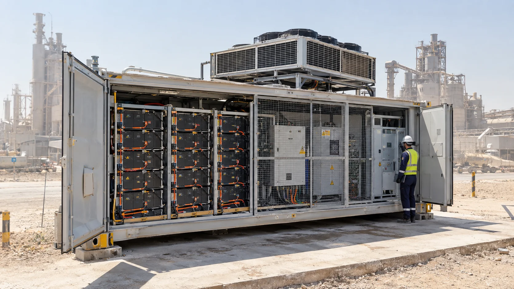
Physically, the layout inside a 20-foot unit is fairly consistent across manufacturers: battery racks line one or both long walls, wired into strings running the container's full DC bus voltage, commonly 1,250 to 1,500 VDC, with the PCS and low-voltage switchgear in a dedicated fire-rated compartment and HVAC on the roof or at one end.
Cells, Modules, and Why LFP Won This Argument
Lithium iron phosphate (LFP) is now the default chemistry for stationary and containerized storage, and the reasoning holds up rather than repeating vendor talking points. LFP's cathode does not reach thermal runaway until roughly 270 to 300°C, well above nickel manganese cobalt oxide's (NMC) onset around 200 to 210°C, and LFP cells commonly outlast NMC by a wide margin at comparable discharge depth. NMC still wins on energy density, which matters for EVs; a stationary container carries no such weight constraint, so LFP's disadvantage there costs nothing.
Cell format has moved faster than chemistry lately. The mainstream cell went from 280Ah prismatic cells to 314Ah, the size behind most of today's roughly 5 MWh 20-foot containers, and makers including CATL, EVE Energy, and Hithium have since pushed prismatic formats well past 300Ah, several now sampling or shipping cells in the 500 to 600Ah range. A larger-format cell packs more energy into the same footprint without adding cell count or busbar joints, the real reason container-level capacity keeps climbing without breaking the roughly 45-tonne road transport limit governing container logistics almost everywhere.
Racks, Busbars, and the Battery Management System Hierarchy
Each rack is a mechanical and electrical unit: modules stacked in a cabinet, connected by busbars sized for the string's fault current, with a rack-level fuse and contactor pair that isolates the entire string without shutting down its neighbors. A container with per-rack disconnects drops one faulted string and keeps most of its capacity online; one wired as an undifferentiated block loses everything behind a single fault.
The BMS governing this structure works in three tiers, each catching a different problem. Slave boards at cell or module level measure voltage and temperature and feed the data upward. A rack-level controller aggregates those readings, runs cell balancing, and opens the contactor on overvoltage, undervoltage, overtemperature, or a lost communication link. A system master sits above every rack controller, aggregates state of charge and health across the container, and interfaces to the PCS and EMS. IEC 62619 sets the baseline safety requirements this hierarchy must satisfy, including BMS functional safety and thermal runaway propagation resistance. Its current second edition tightened those requirements.
A BMS hierarchy that loses a single communication link does not announce itself. It shows up months later as one rack quietly underperforming its neighbors, and by the time a state-of-health report flags the gap, the degradation is already done.
The Power Conversion System: The Real Engineering Argument
The PCS is the bidirectional inverter converting the racks' DC output into grid-compliant AC and back again, setting the hard ceiling on how fast the container can push or absorb power regardless of the energy behind it. A central PCS skid handles the whole output through one or two large inverters, simpler to specify but a single point of failure; string-level architecture puts a smaller inverter on each rack, at a cost premium, so losing one leaves the rest of the container discharging normally.
Silicon carbide MOSFETs are displacing silicon IGBTs in newer PCS designs, switching faster with lower reverse-recovery losses and cutting conduction losses enough to improve round-trip efficiency, a real advantage where every kilogram of cooling load matters. A PCS's rectifier-inverter stage is a close cousin of an industrial variable frequency drive's front end, sharing the same harmonics and cable-length concerns.
The Isolation Transformer, Medium-Voltage Connection, and Protection
Most containerized systems above roughly 500 kW connect to medium voltage rather than a low-voltage bus, and the isolation transformer makes that connection safe, separating the PCS's output from the MV network and blocking DC injection from reaching the grid. Installations overwhelmingly specify dry-type cast-resin transformers, for the same reasons that favor dry-type transformers over oil-filled units in any fire-sensitive application: no oil to contain, no bunding. IEC 60076 sets the general design requirements; typical MV connection points across the Gulf and southern Africa sit at 11 kV, 13.8 kV, or 33 kV.
Each string's DC side carries its own fuse coordinated per IEC 60269-4 and a contactor for controlled disconnection; most Li-ion BESS DC buses run ungrounded or high-resistance grounded, so a single ground fault raises an alarm rather than tripping the system outright. MV-side switchgear must meet IEC 62271-200's requirements above 1 kV, sharing design DNA with a containerized MCC panel's bus and protection scheme, including the arc-flash calculations under IEEE 1584 setting the PPE category on the door. The same coordination behind staged industrial surge protection applies: a relay scheme built for one-directional fault current alone misoperates the first time the container discharges into a fault.
HVAC and Thermal Management: What Changes at 50°C Ambient
Every cooling system on a containerized BESS is rated against a reference ambient, and that number matters more than anything on the datasheet. HVAC sized to an L45/W18°C condition, 45°C air against an 18°C water loop, delivers full rated cooling under real desert heat; the same tonnage validated only at a milder reference loses capacity once ambient spikes past that threshold, right when the battery needs it most. Gulf air routinely exceeds 45°C in summer and has been recorded above 50°C in Kuwait and Saudi Arabia, and an unshaded roof runs hotter still, since direct solar load on bare sheet steel routinely adds 20 to 30°C on top of the surrounding air temperature, so a rooftop condenser fights a hotter effective ambient than the weather station ever reports.
A container HVAC system sized off the ambient temperature on a weather report, rather than the actual skin and condenser temperature it will see in full sun, is sized wrong before it is even ordered.
The consequence is capacity, not comfort: HVAC becomes a large parasitic load exactly when the system is asked to do the most work, since cooling and discharge demand peak on the same afternoon, and every kW HVAC draws is unavailable at the point of interconnection. Liquid cooling holds a real advantage beyond cell-to-cell uniformity: variable-speed pumps draw less parasitic power than constant-running fans against 45°C-plus air, and a sealed coolant loop sidesteps the desert dust that clogs air-cooled condenser fins fast enough to make IP55-or-better enclosures a real requirement. Tighter rack-level uniformity also means every cell ages at a closer rate, the real mechanism behind liquid-cooled racks outliving forced-air racks at comparable cycling. At the opposite extreme, a Russian-winter container needs the system reversed, keeping cells above the roughly 0°C floor where LFP charge acceptance drops off sharply: sizing HVAC against both tails is what separates a resilient battery energy storage system design from one that only works on a mild day.
Fire Detection and Suppression: Detection, Large-Scale Testing, and Explosion Control
Fire protection inside a containerized BESS starts with detection, not suppression: off-gas sensors tuned to the gases an LFP cell vents before reaching thermal runaway buy the minutes needed to isolate a faulted rack before it propagates. NFPA 855 requires a Hazard Mitigation Analysis, the formal study of how a worst-case failure would behave, for most installations above its size thresholds, pushing fire-engineering input earlier into the design than most schedules assume.
UL 9540A evaluates thermal runaway fire propagation at cell, module, unit, and installation level, and NFPA 855 leans on that data directly: where a container cannot meet the standard's prescribed separation distances from other equipment, a large-scale UL 9540A test showing fire does not jump to the container next door justifies a tighter layout instead of relying on spacing tables alone. Explosion protection splits between two philosophies, deflagration venting sized to NFPA 68 and active gas detection that dilutes off-gas before it reaches an explosive concentration, the choice driven by enclosure volume and ventilation design. Suppression splits along familiar lines, water-mist for surface cooling and clean-agent for switchgear compartments; insurers across the Gulf and South Africa now ask for the UL 9540A test report during permitting, not a compliance letter.
Containerized BESS Components at a Glance
This table lists the battery energy storage system components that have to work correctly together, the battery energy storage system diagram most proposals leave incomplete, before the container ever discharges into a real fault or a real heatwave.
| Component | Core Function | Governing Standard |
|---|---|---|
| Cells and modules | Store energy; LFP dominant for stationary duty | IEC 62619 |
| Racks and busbars | Structure modules into strings; per-string isolation | IEC 62619 |
| Battery Management System | Cell, rack, and system-level protection and balancing | IEC 62619 |
| Power Conversion System | Bidirectional DC-AC conversion, grid synchronisation | IEC 62933-5-2 |
| Isolation transformer | Galvanic separation, MV step-up | IEC 60076 |
| MV switchgear and protection | Fault isolation, relay coordination | IEC 62271-200 |
| HVAC / thermal management | Holds cells inside their rated temperature window | NFPA 855 |
| Fire detection and suppression | Off-gas detection, propagation prevention | NFPA 855 / UL 9540A |
| Energy Management System | Dispatch: peak shaving, solar, backup, arbitrage | Grid code / interconnection agreement |
The Energy Management System: Dispatch Logic on Top of Everything
Every component on that table can be specified correctly and the installation still underperforms if the EMS makes the wrong call on charging and discharging. It sits above the BMS and PCS, turning site load, tariff structure, and on hybrid sites the solar forecast and generator status into a dispatch command issued every few seconds.
A few objectives cover most industrial installations, and a single EMS increasingly juggles more than one. Peak shaving and demand-charge management discharge against the metered peak, sized against real interval data, not a monthly bill. A solar battery energy storage system adds self-consumption: charging from excess PV that would otherwise be curtailed, then discharging after sundown, a shape now common across hybrid sites in Saudi Arabia, the UAE, and Oman. Diesel-hybrid dispatch smooths the genset's loading instead of letting it idle or overload, the real source of fuel saving. Forecasting algorithms earn their keep in the gap between objectives, since a solar forecast wrong by 15 percent strands capacity exactly when it is needed.
South Africa's grid context has genuinely shifted: Eskom has kept the national grid free of formal, stage-based load shedding since May 2025, its longest stable stretch in years, as new generating capacity came online and the coal fleet's maintenance backlog worked down. That does not make outage-response dispatch obsolete, only more specific: localized, feeder-level outages still happen independent of national load shedding, and a plant that sized its BESS as blackout insurance during the worst shedding years now gets more value re-tasked toward demand-charge management and time-of-use arbitrage, outage ride-through now a secondary mode rather than the primary job.
How Long Does a BESS Last?
Most warranty documents answer this with one number: roughly ten years, with 60 to 70 percent of nameplate capacity guaranteed at term end. That number describes the cells, not the container.
In practice, several balance-of-plant parts wear out before the chemistry does. Electrolytic capacitors in the PCS's DC-link stage have a design life driven by internal temperature, typically 8 to 12 years, shorter than the battery warranty around them. HVAC compressors and fans are mechanical, cycling parts that wear out faster running near-continuously against 50°C ambient than in a mild climate. None of this shows on a cell-degradation curve, or gets fixed by a battery augmentation programme five years in. A containerized battery energy storage system built to last its design life needs a maintenance plan tracking these wear items on their own schedule, not one assuming the container stops ageing once the warranty is signed.
What Does a Containerized BESS Cost?
Every battery energy storage system cost estimate should map back to the components above, not one blended per-kWh figure: hardware cost and total project cost use different denominators that should never be mixed. Within hardware cost alone, cells and modules typically run 50 to 60 percent, the PCS 15 to 20 percent, thermal management 5 to 8 percent, and the remainder, enclosure, BMS, switchgear, and wiring, makes up the rest. Cell prices keep falling: BloombergNEF's annual battery price survey has tracked pack pricing down from over $150 per kWh earlier in the decade to under $115 per kWh by the mid-2020s, LFP cell pricing lower still.
Total project cost is a wider number again: hardware makes up 60 to 75 percent of it, the rest split across engineering, permitting, civil works, and installation labour, what EPCs bundle as balance of system. Benchmarks from BloombergNEF and Wood Mackenzie put turnkey containerized systems, 100 kWh to several-MWh scale, at roughly $180 to $320 per kWh installed, a battery energy storage system cost that puts a 1 MW / 2 MWh liquid-cooled container between $360,000 and $640,000 depending on cooling type and cell format. Smaller behind-the-meter systems carry a real premium per kWh, since fixed costs like the PCS do not shrink with battery size. Sourcing cells, PCS, and switchgear through verified channels rather than grey-market suppliers protects the certification paperwork an insurer will ask for; component sourcing discipline matters here as much as on any other equipment.
A Real-World Scenario: Thermal Derating at a Gulf Cement Plant
A cement plant in Saudi Arabia's Eastern Province installed a containerized BESS beside a rooftop solar array to shave the demand charge its raw-mill motors generated starting each morning. The HVAC was rated against a 35°C reference ambient, standard for the vendor's default line, not the L45-class rating the site's summer conditions called for, and the container sat on an unshaded concrete pad next to the mill building, where the EPC's civil layout put it for cable-run convenience.
Through the first two summers, the system did what it was sized to do. By the third, cell capacity had degraded and ambient conditions had run hot enough that the BMS began derating discharge power on the hottest afternoons, precisely when the raw mills were starting and the demand charge it existed to shave was happening. The peak-shaving guarantee lapsed for the two or three hours a day when it mattered most, and the demand charge came back.
The fix was not a new BMS or new cells. It was a shade structure over the roof, a refrigerant-loop upgrade closer to an L45/W18 rating, and an EMS dispatch change pre-charging the racks earlier each morning rather than assuming full power regardless of the roof's skin temperature at two in the afternoon. The retrofit cost a fraction of the original HVAC line item; specifying the correct ambient rating up front would have cost nothing.
The cheapest fix for a thermally derated BESS is the one made on the datasheet before the container ships. Every fix made after that involves a crane, a shade structure, or a lapsed performance guarantee.
None of the battery energy storage system components covered here are exotic in isolation. Isolation transformers, MV switchgear, protective relaying, HVAC, and dispatch logic are things a competent electrical engineering team specifies correctly for conventional plant equipment daily; a containerized BESS just asks all of them to agree with each other, and with a lithium battery's thermal and fault behaviour, inside one steel box. Where that coordination breaks down is almost always at the interface between systems designed on different assumptions, which is exactly the gap a dedicated electrical engineering review closes before a container is ordered, matching transformer, protection, and thermal design against the conditions the installation will actually see.
Frequently Asked Questions
What components make up a BESS?
A containerized BESS is built from nine subsystems: cells and modules, racks, a battery management system, a power conversion system, an isolation transformer and MV switchgear, low-voltage protection, HVAC or liquid cooling, fire detection and suppression, and an energy management system that decides when it charges or discharges. Most vendor diagrams show only the battery, inverter and transformer; the other five are what actually determine whether the system meets its output guarantee.
What is inside a BESS container?
Inside a typical 20-foot unit, battery racks line one or both long walls wired into strings running the container's full DC bus, commonly 1,250 to 1,500 VDC, with the power conversion system and low-voltage switchgear in a dedicated fire-rated compartment and HVAC mounted on the roof or at one end.
How long does a BESS last?
Warranty documents typically guarantee 60 to 70 percent of nameplate capacity after roughly ten years, but that figure describes the cells, not the container. Balance-of-plant parts such as PCS capacitors and HVAC compressors commonly wear out sooner and need their own maintenance schedule.
What does a containerized BESS cost?
Hardware alone typically splits as 50 to 60 percent cells and modules, 15 to 20 percent power conversion, and 5 to 8 percent thermal management. Turnkey installed cost benchmarks run roughly USD 180 to 320 per kWh, putting a 1 MW / 2 MWh container between USD 360,000 and 640,000 depending on cooling type and cell format.
Related products
Components from our catalogue relevant to this article — request a quote for availability, lead time and pricing.
/TC625 AF100 ABB - Coaxial Modem 3BSE002224R1.png "ABB TC625 AF100 ABB - Coaxial Modem 3BSE002224R1 | Coaxial modem TC625 AF100")
TC625 AF100 ABB - Coaxial Modem 3BSE002224R1
Coaxial modem TC625 AF100
/SB512 ABB - Power Supply 3BSE002098R1.png "ABB SB512 ABB - Power Supply 3BSE002098R1 | SB512 power supply module")
SB512 ABB - Power Supply 3BSE002098R1
SB512 power supply module
/DSSS 171 ABB - Voting Unit 3BSE005003R1.png "ABB DSSS 171 ABB - Voting Unit 3BSE005003R1 | DSSS 171 voting unit for safety systems")
DSSS 171 ABB - Voting Unit 3BSE005003R1
DSSS 171 voting unit for safety systems
/4NWP100174R0001 ABB - UPS PowerValue 11LI Up 2000 VA.webp "ABB 4NWP100174R0001 ABB - UPS PowerValue 11LI Up 2000 VA | UPS PowerValue 11LI Up 2000 VA")
4NWP100174R0001 ABB - UPS PowerValue 11LI Up 2000 VA
UPS PowerValue 11LI Up 2000 VA