
Explosion Proof Lighting, Junction Boxes, and Distribution Boards vs Standard Electrical: What Actually Changes

Quick Answer
Explosion proof lighting, junction boxes, and distribution boards work by containing and quenching an internal ignition inside a machined flameproof enclosure, not by sealing hazards out. This guide covers NEC vs IEC/ATEX classification and exactly what changes in housing, joints, and thermal design once Ex-rated equipment is required.
A lot of procurement requests come in asking for "sealed" or "weatherproof" gear for an area that's actually classified hazardous, and the two words get treated as interchangeable when they aren't. Explosion proof lighting, explosion proof junction boxes, and explosion proof distribution boards aren't just tougher, better-gasketed versions of standard equipment. They work on a different physical principle, they're certified against a different test standard, and specifying a NEMA 4X enclosure where the site needs Ex d equipment is a decision that can get someone hurt. This post covers what "explosion proof" physically means, when hazardous area classification actually requires it, and what changes in the light fixture, the junction box, and the distribution board once that requirement applies.
A sealed enclosure keeps the weather out. An explosion-proof enclosure is built to let an explosion happen inside it and stop there.
What "Explosion Proof" Actually Means
The term gets used loosely on spec sheets and site walks, and that looseness causes real problems. A standard IP66 or NEMA 4X enclosure is sealed against dust and water. It isn't designed to contain an internal explosion, because nobody expects flammable gas to get inside a sealed box in the first place. Explosion-proof equipment starts from the opposite assumption: gas or vapor will eventually find its way inside, an arcing contact or hot component will eventually ignite it, and the enclosure's job is to survive that ignition without passing it to the atmosphere outside.
Containment and Quenching, Not Prevention
The formal protection concept, defined in IEC 60079-1 and referenced in NEC Article 500 as "explosionproof apparatus," is called flameproof enclosure, marked Ex d. It doesn't try to keep gas out. It assumes an internal explosive mixture will ignite, and it's built to contain the pressure of that explosion without rupturing, cool the escaping combustion products enough that they can't re-ignite the surrounding atmosphere, and physically block flame propagation through every gap, joint, and cable entry in the housing.
That last part is where the engineering lives. A flameproof joint isn't sealed with a gasket. It's a long, narrow, precisely machined metal-to-metal path that forces hot combustion gases to travel through a gap so tight, over a length long enough, that they lose their ignition energy before reaching open air. It's the same principle behind a wire gauze flame arrestor: enough contact surface in a narrow enough passage strips the heat out of escaping gas before it can propagate.
A device rated explosion proof isn't claiming ignition inside it can't happen. It's claiming that if ignition happens, the consequence stops at the enclosure wall. That should change how you evaluate every component going inside one of these enclosures, because none of them get a pass on generating heat or a spark just because the box is Ex-rated. We field this mix-up constantly in industrial electrical services work, usually after someone specifies the wrong enclosure for the area.
Hazardous Area Classification: Why This Even Applies
None of this matters unless the area actually qualifies as hazardous. Overspecifying explosion proof lighting and switchgear wastes budget and adds maintenance burden. Underspecifying it in a classified area is a life-safety failure waiting for the right day. Two classification systems govern the decision.
Class and Division: NEC Articles 500-506
Under NFPA 70, hazardous locations are classified by Class, Division, and Group. Class I covers flammable gases and vapors, Class II covers combustible dust, Class III covers ignitable fibers and flyings. Division 1 means the hazardous concentration is present under normal operating conditions; Division 2 means it's only present under abnormal conditions, like a seal failure or process upset. Article 500 codifies the Class/Division system, while NEC Articles 505 and 506 introduced the Zone-based alternative for gas and dust locations, aligned with international practice so a facility running globally sourced Ex-rated equipment doesn't have to force a mismatch between frameworks. Groups A through G further narrow the classification by the specific gas or dust, since acetylene and methane don't behave the same way inside a flameproof joint.
The Zone System: IEC 60079 and ATEX
Outside North America, and increasingly inside multinational facilities in North America too, hazardous areas are classified using the Zone system in IEC 60079. Zone 0 covers areas where an explosive atmosphere is present continuously or for long periods. Zone 1 covers areas where it's likely during normal operation. Zone 2 covers areas where it's unlikely, and brief if it occurs. Dust hazards get the same tiering under Zones 20, 21, and 22. In the EU, the ATEX Directive 2014/34/EU governs the equipment side, requiring Ex-marked gear with Equipment Protection Levels (Ga, Gb, Gc for gas; Da, Db, Dc for dust) that map to the zone the equipment is rated for.
Roughly, Division 1 covers ground occupied by both Zone 0 and Zone 1, and Division 2 lines up with Zone 2, but "roughly" is the operative word. The two systems aren't calculated the same way, and equipment certified under one scheme isn't automatically valid under the other without a documented equivalency. Our earlier piece on Ex d vs Ex db marking covers reading the nameplate once you know which framework applies; worth a read before signing off on any Ex-rated purchase order.
The classification itself comes from a documented hazardous area study, not a guess based on what's stored nearby. A tank farm, a wastewater digester generating methane, and a solvent-based paint booth all get classified differently, and the boundaries and gas group involved are specific to that facility's process data. If that study doesn't exist or hasn't been updated since the last process change, that's the first gap to close, not the fixture selection. We handle this as part of broader electrical engineering scope on hazardous-area projects, because a wrong classification upstream makes every downstream equipment decision wrong with it.
Explosion-Proof Light Fixtures vs Standard Light Fixtures
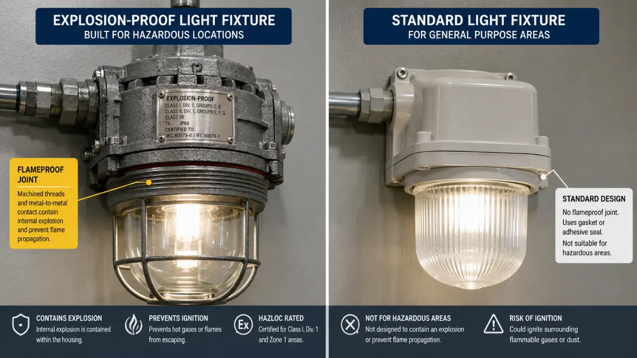
Explosion proof lighting is where this distinction shows up most in field walks, because a standard high-bay fixture and an explosion proof light fixture can look similar from the ground. They aren't interchangeable, and the differences go well past the housing.
Housing Material, Wall Thickness, and Flameproof Joint Tolerances
A standard fixture uses stamped sheet steel or aluminum, typically 1 to 2 mm thick, held together with screws and a gasket for weather sealing. An explosion proof light fixture uses a cast, copper-free aluminum or malleable iron body with wall sections commonly running from around 5/8 inch up past an inch at the cover and threaded entries, because the housing has to survive internal explosion pressure without deforming or cracking.
The joint between globe and body is machined to the flameproof joint tolerances in IEC 60079-1, a precision metal-to-metal flame path rather than a gasketed seal, with permitted gap width and minimum joint length varying by gas group. Group IIC equipment, rated for hydrogen and acetylene, requires the tightest tolerances of the three groups, with gaps controlled to a few hundredths of a millimeter over a specified minimum length, because those gases propagate flame through narrower gaps than propane or methane do. A machining tolerance that would be irrelevant on a standard fixture housing is the entire safety mechanism on an explosion-proof one.
Glass and Lens Rating
A standard fixture's lens is chosen for light transmission and impact resistance under normal handling. An explosion-proof fixture's globe is a structural pressure-retaining component. It has to survive the internal explosion pressure pulse without shattering, and maintain that flameproof joint tolerance against the metal frame holding it. Most globes are heat- and impact-resistant borosilicate glass, seated in the housing with a machined retaining ring, not a snap-fit bezel. Swapping in a generic replacement lens because it "fits" voids the certification even if it looks identical, since the certificate covers the tested assembly, not the individual part.
Heat Dissipation: What a Sealed Fixture Can't Vent Away
This is the part that catches people used to specifying standard LED fixtures. A standard high-bay sheds heat partly by convection around an open or louvered housing. Explosion proof LED lights can't do that. The housing stays sealed to maintain the flameproof joint, so every watt the driver and LED array generate has to conduct out through the cast metal body, with no fan and no vented path.
That constrains the design more than most people expect. Explosion proof LED lights run at lower drive currents relative to their thermal capacity than an equivalent open-air fixture, and the housing mass and fin geometry are engineered around the LED manufacturer's thermal derating curve for the fixture's rated ambient range. A fixture rated for a T4 temperature class has to keep its hottest external surface below 135°C even under worst-case ambient and full load, because that surface temperature has to stay below the autoignition temperature of the gas group it's certified for. Retrofitting a higher-lumen LED array into an existing housing without redoing that thermal analysis is a common mistake, and one that should never happen in the field without engineering sign-off.
Explosion-Proof Junction Boxes vs Standard Junction Boxes
Junction boxes get treated as commodity items on most jobs, and in unclassified areas that's reasonable. In a classified area, an explosion proof junction box is a certified pressure vessel with terminals inside it, specified with the same rigor as the fixture it feeds.
Flameproof Joint Machining on the Box Itself
A standard cast or fabricated JB uses a gasket and a cover plate, fine for keeping out dust and splash. An explosion proof junction box uses a machined flameproof joint at the cover and at every conduit or cable entry. The cover typically bolts down at multiple points around its perimeter rather than a few corner screws, because maintaining even joint pressure across the whole flame path is part of what keeps the tolerance within spec. A cover that's warped, corroded, or unevenly bolted can open the joint gap beyond its certified limit without anyone noticing until it's tested.
Certified Cable Glands, Not Generic Ones
This is one of the most commonly missed items on hazardous-area installations. A standard cable gland just needs to grip the cable and seal against moisture. A cable entry into an explosion-proof junction box has to satisfy IEC 60079-1's Clause 13 requirements on top of the general gland requirements in IEC 60079-0, because the gland becomes part of the flame path if gas migrates in along the cable. That typically means a barrier gland filled with certified sealing compound, or a standard gland used only with solid, non-wicking cable construction the certification allows. Running armored cable with a loose-lay inner construction through a compression gland rated for a different cable type is a certification violation even if the joint looks mechanically sound, because the gland's Ex certificate is tied to the tested cable type, not the thread size.
Potting and Sealing Methods
Terminal potting compound inside an explosion proof junction box isn't there for vibration resistance. It eliminates void space where gas could accumulate and fixes conductor position so a loosened terminal can't create an arcing gap. Where potting isn't used, a certified sealing fitting installed within the required distance of the box, per the equipment's certificate of conformity, blocks gas migration along the conduit run instead. Our earlier post on grounding and bonding in panel systems covers how bonding gets handled generally; inside an Ex-rated junction box that bonding conductor still has to enter and terminate without compromising the flameproof joint or the certified gland, a detail that trips up crews used to standard practice.
Explosion-Proof Distribution Boards vs Standard Distribution Boards
Distribution boards carry the highest consequence of the three, because a DB houses multiple energized circuits and breakers capable of interrupting real fault current.
Internal Arc Containment
A standard distribution board assumes any arcing fault gets cleared fast enough that the enclosure only has to contain a brief, low-energy event; it isn't designed to contain a sustained internal explosion. An explosion proof distribution board has to assume ignition of a flammable atmosphere inside the enclosure, from an arcing terminal, a loose lug, or a failing breaker, and contain the full pressure and thermal event the same way the junction box and light fixture do. Some manufacturers achieve this with a heavy cast or fabricated Ex d enclosure around standard off-the-shelf breakers; others use a component-barrier approach where each breaker sits behind its own small flameproof barrier inside a lighter overall enclosure. Both are certified, tested assemblies, not something a panel shop can improvise by welding a heavier box around commodity breakers.
Breaker Derating Inside a Sealed Enclosure
Breakers generate heat proportional to the square of current carried, and in a standard panelboard that heat has somewhere to go: convection inside a ventilated enclosure, sometimes a fan. Inside a sealed explosion-proof distribution board, none of that airflow exists. Heat has to conduct out through the enclosure wall, and manufacturers commonly derate breaker continuous current well below its open-air nameplate rating, often in the range of 15 to 25 percent, to keep internal temperature rise within both the breaker's insulation rating and the enclosure's certified T-class. Specify a 100-amp frame at full nameplate current inside an Ex d enclosure without checking the manufacturer's derating tables and you'll get nuisance tripping at best, a certification violation at worst, because internal operating temperature was never verified against the T-rating during design.
Thermal Management as a Design Discipline
Because a sealed Ex enclosure can't vent, thermal management gets designed in at the layout stage: breaker spacing to avoid stacking heat sources, conductor sizing generous enough to limit I²R losses with no airflow, and sometimes a heat sink plate or added enclosure mass to absorb the worst-case load without exceeding the temperature class. It's the same discipline behind containerized MCC panel design, where heat load calculations against the actual equipment inside the box decide whether the enclosure holds its rating under full load. Get that calculation wrong on an Ex-rated board and you don't just get a hot panel. You get a board that no longer meets the certification it was sold under.
Component Comparison
| Component | Standard Version | Ex-Rated Version | Key Design Difference |
|---|---|---|---|
| Light fixture | Stamped steel/aluminum, 1-2 mm wall, gasketed lens | Explosion proof light fixture, cast aluminum body, borosilicate globe | Machined flameproof joint at globe and hood; heat conducts through solid metal, no venting |
| Junction box | Cast or fabricated body, gasketed cover, generic cable gland | Explosion proof junction box, machined flame-path cover, IEC 60079-1 Clause 13 certified glands | Flame path tolerance at every joint/entry; potting or certified sealing fittings block gas migration |
| Distribution board | Sheet steel panelboard, ventilated or fan-assisted | Explosion proof distribution board, Ex d cast enclosure or component-barrier design | Breaker current derated 15-25% for sealed thermal rise; enclosure sized to contain internal arc pressure |
| LED driver/lamp | Open-air convection cooling, full manufacturer lumen rating | Explosion proof LED lights, conduction-cooled to housing mass | Drive current limited by T-class surface temperature, not just the LED datasheet maximum |
A Real-World Scenario: The Retrofit That Skipped Classification
A mid-size chemical blending facility upgraded warehouse lighting from metal halide to LED to cut energy costs, straightforward everywhere except one corner: a solvent transfer and drum-filling area next to the main warehouse, separated only by a half-height partition with no door. That area had been classified Class I, Division 2 during the original buildout, but the classification drawing never made it into the maintenance team's retrofit scope. The contractor priced and installed standard IP65 LED high-bays across the whole site, including over the drum-filling stations, because from the floor they looked identical to fixtures already hanging in the unclassified warehouse.
Six weeks after commissioning, a process safety audit flagged the fixtures during a routine hazardous-area inspection. None of the new units carried Class I, Division 2 certification. They were sealed against dust and moisture, but sealed isn't explosion proof, and Division 2 still requires suitable equipment even though the hazardous concentration is only present under abnormal conditions, like a spill during transfer. A relay contact inside a standard driver, energizing hundreds of times a day, was now sitting directly above a station where solvent vapor could accumulate during exactly the kind of event Division 2 exists to plan for.
The facility pulled every fixture over the drum-filling area, verified the boundary against the original classification study, and replaced them with certified explosion proof LED lights carrying the correct Division 2 rating and gas group, plus explosion proof junction boxes at every connection point inside the boundary. The rework cost roughly four times what correct fixtures would have cost as the initial spec, not counting two weeks of lost schedule sourcing replacements under a temporary hot-work restriction.
The classification boundary doesn't move because a fixture looks rated enough from the floor. Verify it against the documented study before a single unit ships to site.
The root cause wasn't bad fixtures. It was a retrofit scope that treated lighting as a like-for-like swap instead of confirming the area classification first. If your classification study predates the last process change on site, contact our team before the next retrofit gets scoped.
Getting the Spec Right the First Time
None of this is exotic engineering, but it has to happen before the purchase order goes out, not after a fixture is already hanging over a classified area. Confirming the Class/Division or Zone rating, matching the gas or dust group and temperature class to the actual process hazard, and sourcing certified explosion proof lighting, junction boxes, and distribution boards from manufacturers with real test documentation are what protect the schedule and the people on site. Techno Control Corp sources and specifies hazardous-area electrical equipment on projects like this, and we carry Ex-rated fixtures, boxes, and boards from manufacturers with verifiable ATEX and IECEx documentation through our products line. If you're scoping a classified-area project or want a second look at an existing installation's classification paperwork, reach out and we'll walk through it with you.
Related products
Components from our catalogue relevant to this article — request a quote for availability, lead time and pricing.
/BAT53 Series Explosion Proof Led Flood Light 70W-1000W For Hazardous Areas.webp "ATEX BAT53 Series ATEX - Explosion Proof LED Flood Light 70W-1000W | Explosion-proof LED floodlight, 70W-1000W")
BAT53 Series ATEX - Explosion Proof LED Flood Light 70W-1000W
Explosion-proof LED floodlight, 70W-1000W
/BAT85 Series Explosion Proof Floodlights , ATEX Led Flood Light.webp "ATEX BAT85 Series ATEX - Explosion Proof Floodlight, LED Flood Light | ATEX-certified explosion-proof LED floodlight")
BAT85 Series ATEX - Explosion Proof Floodlight, LED Flood Light
ATEX-certified explosion-proof LED floodlight
/BnT81 Series Aluminium ATEX Floodlights , Hazardous Location ights with 400W~1000W.webp "ATEX BnT81 Series ATEX - Aluminium Floodlight, Hazardous Location Lighting 400W-1000W | Aluminium ATEX floodlight, 400W-1000W")
BnT81 Series ATEX - Aluminium Floodlight, Hazardous Location Lighting 400W-1000W
Aluminium ATEX floodlight, 400W-1000W
/HRD91-LED Series Explosion Proof LED Lighting 30W 50W 70W 100W For Hazardous Areas.webp "ATEX HRD91-LED Series ATEX - Explosion Proof LED Lighting 30W-100W | Explosion-proof LED light, 30W/50W/70W/100W")
HRD91-LED Series ATEX - Explosion Proof LED Lighting 30W-100W
Explosion-proof LED light, 30W/50W/70W/100W