
Ring Main Units and MV Switchgear: How Industrial Sites Distribute Medium Voltage

Quick Answer
A ring main unit decides whether a single medium-voltage cable fault takes down one building or the whole site. This guide traces MV distribution from the ring main unit and its SF6 alternatives through relay coordination to where the LV motor control center picks up.
A ring main unit is the piece of switchgear that decides what happens when a medium-voltage cable faults: does one building go dark for an afternoon, or does the site barely notice? That's why what a ring main unit actually does, and doesn't do, matters more than most procurement checklists ever cover. Get the RMU right and a fault costs a few minutes of switching. Skip the maintenance that keeps it honest, and the same fault costs a shift.
This piece traces medium-voltage power the way it moves on an industrial site: through the ring main unit, its relay coordination with the transformer, the compact secondary substation housing the assembly, and down to where the motor control center picks up. We've already covered what's inside a containerized MCC panel in detail; this post stops where that one starts, at the transformer's LV terminals, and covers everything upstream of it.
What Is a Ring Main Unit?
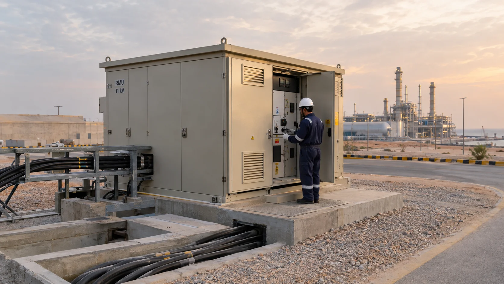
A ring main unit (RMU) is a factory-assembled, metal-enclosed switchgear package installed at a single load point on a medium-voltage ring distribution network. It typically holds two or three switching "ways" in one gas- or air-insulated enclosure: two ring ways connecting to the incoming and outgoing ring cable, and one transformer way, or tee, feeding the site's own step-down transformer. A fourth way, for metering or a spare feeder, is common enough that Gulf utility designs specify RMUs in three- or four-way configurations as standard.
Physically, an RMU is small, rarely bigger than a filing cabinet, since the switching mechanism sits inside a sealed enclosure rather than the open, walk-in bus structure of a full substation. That's the point: it installs at dozens of load points around a network without a dedicated building at each one.
The complete assembly is type-tested under IEC 62271-200, covering switchgear from above 1 kV up to 52 kV, though most RMUs sold into industrial networks are built for 7.2 kV to 36 kV, matching the 11 kV, 13.8 kV, 22 kV and 33 kV ring voltages in use across Gulf and South African networks. South Africa formalizes this with its own ring main unit standard, SANS 1874, descended from Eskom's NRS 006 specification and sitting alongside SANS 62271-200, the national adoption of the IEC assembly standard.
What Is the Difference Between an RMU and a Substation?
An RMU is a single piece of switchgear at one point on a ring. A substation is the facility built around it: the transformer, the LV switchboard, earthing, and civil works, usually with an RMU as its MV switching element. Every compact secondary substation contains an RMU, but an RMU alone is not a substation. Add a transformer, an LV panel, and an enclosure, and that's a compact secondary substation, covered further down.
Why a Ring Beats a Radial Feed for Continuity
A radial feeder has one source and one path. If the cable faults anywhere along it, every downstream load loses power until the fault is found and repaired, which on a buried MV cable can take hours. A ring changes that math: every load point has two paths back to source, so a fault on one section is isolated by opening the RMUs bracketing it, and the rest of the ring gets restored from the other direction instead.
Distribution networks are built meshed but operated radially: utilities close enough switches to form a physical ring, then leave one point, the normally open point, open so each section is fed from one direction only. When a fault happens, the two RMUs bracketing it open, the normally open point closes elsewhere on the ring, and supply is restored to everyone except the short section under repair. Done manually, that's minutes with a switching crew; done with motorized RMUs and a fault passage indicator reporting to a control room, it's seconds.
A ring main unit doesn't prevent faults. It exists so a fault costs one section of cable instead of the whole feeder.
The tradeoff is cost: a ring needs more cable, more switching points, and a protection scheme that correctly identifies which section faulted, harder than a simple radial fuse-and-forget design. For a single non-critical building that complexity isn't worth it; for a process plant where an unplanned shutdown costs more than the extra switchgear, it almost always is.
Inside the RMU: Insulation Media and Switching Functions
What Gas Is Used in a Ring Main Unit?
Most ring main units in service today are insulated and arc-quenched with sulfur hexafluoride, SF6, chosen for its dielectric strength and its ability to absorb and cool a switching arc, letting manufacturers shrink what would otherwise need a larger air gap into a compact, sealed enclosure, the reason RMUs became a mass-deployed product from the 1970s onward.
The problem is what SF6 does if it leaks: a 100-year global warming potential of roughly 23,500 times that of CO2, per the IPCC's fifth assessment report. A single RMU holds only a few kilograms of gas, but multiplied across a network of thousands of units as seals degrade, the cumulative exposure is what regulators now target.
Two alternatives are commercially mainstream. Solid-dielectric RMUs, such as ABB/Hitachi Energy's SafeRing and SafePlus platforms, encapsulate busbars and vacuum interrupters in cast epoxy, removing gas entirely. Clean-air designs, including Schneider Electric's AirSeT range and Siemens' Blue GIS 8DJH series, use dry air or an air-based mixture with a GWP below 1, paired with vacuum interruption for the switching duty. Air-insulated switchgear (AIS), the oldest approach, avoids gas handling but needs a larger footprint, suiting outdoor yards with room to spare more than a compact kiosk substation.
Switch-Disconnectors, Fused Tees and Vacuum Circuit-Breaker Ways
The insulation medium is only half the picture: what decides how an RMU behaves in a fault is which switching device sits in each way, and vendors mix three functions inside one enclosure.
A switch-disconnector is a load-break device: it makes and breaks normal load current and gives a reliable open point for isolation, with no fault-breaking duty. Ring ways are almost always switch-disconnectors, built to IEC 62271-103, since the ring's own protection, not the ring way, clears the fault.
A fused switch-disconnector, or fused tee, adds current-limiting HV fuses in series with the switch. Built to IEC 62271-105, it's the traditional way to protect a smaller transformer: the switch handles on/off duty, the fuse clears a fault without a relay. It's cheap, but just as simple: fuses don't discriminate against inrush, don't report status, and don't support auto-reclosing.
A vacuum circuit-breaker way, built to IEC 62271-100, is the only one of the three with a genuine fault-breaking rating, always paired with a relay. CB ways cost more and need a trip supply, but they're the only option once a transformer is large enough that fuse discrimination becomes impractical, or the site wants remote tripping, auto-reclose, or real coordination.
| Function | Switch-disconnector (ring way) | Fused switch-disconnector (fused tee) | Vacuum circuit-breaker (CB way) |
|---|---|---|---|
| Breaks normal load current | Yes | Yes | Yes |
| Breaks fault current | No, relies on the ring's protection | Yes, via the HV fuse | Yes, on its own |
| Needs a protection relay | No | No | Yes, always |
| Governing IEC standard | IEC 62271-103 | IEC 62271-105 | IEC 62271-100 |
| Typical duty | Ring in/out switching | Smaller transformer protection | Larger transformer or feeder, auto-reclose |
SF6, the F-Gas Regulation and Where RMUs Are Headed
The regulatory pressure on SF6 is real, even where it doesn't originate from Gulf or South African law. The EU's revised F-gas regulation, Regulation (EU) 2024/573, entered into force in March 2024 and phases out new SF6-insulated switchgear in stages: MV switchgear up to 24 kV ordered after that date must be in service before 1 January 2026, and switchgear above 24 kV up to 52 kV gets until 1 January 2030. Neither SEC, DEWA, ADDC nor Eskom mandates this timeline, though all four maintain approved-vendor lists any RMU must clear first. But every major manufacturer sells into Europe and runs one product line, not two: Schneider, Siemens, and ABB/Hitachi Energy have all moved their flagship ranges to SF6-free platforms as the default catalog item, which shapes what's easiest to source regardless of local regulation.
The honest tradeoff: solid-dielectric and clean-air RMUs cost more today than equivalent SF6 RMU switchgear, and don't yet carry SF6's five-decade field record in harsh, high-salinity sites. Against that, they remove gas handling and end-of-life gas recovery from the maintenance budget entirely, no small saving across a network of RMUs.
Specifying SF6 by default because it's what's always been ordered is no longer a neutral decision. It's a decision to keep a gas-handling obligation that a solid-dielectric or clean-air alternative removes outright.
Cable Terminations and the Elbow Connectors That Actually Fail
An RMU is only as good as the connection between its bushings and the incoming cable, and that's where a surprising share of field failures start. Most MV ring cables terminate through separable insulated connectors, or elbows, built to IEEE 386 for systems from 2.5 kV to 35 kV: loadbreak elbows (around 200 A) isolate a ring way under load, while deadbreak elbows (around 600 A) need the circuit dead first and suit higher current or a bolted joint.
The failure mode that shows up repeatedly on site isn't the elbow itself, it's the installation: an under-torqued connection, a lug crimped with the wrong die, or a screen not bonded to the elbow's shield, any of which runs hot and eventually flashes over years after commissioning. Uncapped spare bushings or UV-degraded boots are the other recurring cause, letting moisture into a bushing never meant to stay open, and neither defect shows on a factory test report.
Protection and Relay Coordination Between the RMU and the Transformer
Getting the switching device right only helps if it trips in the correct order relative to everything else on the ring and behind the transformer. A fused tee's protection is fixed the day the fuse is chosen: too close to magnetizing inrush and it nuisance-trips on energization; too far above full-load current and it won't clear a low-level winding fault fast enough, with no adjustment afterward beyond swapping the fuse itself.
A CB way gives a relay to tune instead: it must grade correctly against both the RMU's own upstream protection and the utility's protection further back, so a fault inside the plant trips the plant's own breaker first, not a recloser three sections away. Getting that margin wrong is exactly what a protection coordination study catches before commissioning; it's the core of our power system audits and optimization work.
Fault passage indicators (FPIs) fitted to each way make ring restoration fast: an FPI doesn't clear a fault, it tells a crew or SCADA which section the fault current passed through, narrowing a search through several RMUs down to the two that bracket it. None of this replaces testing the transformer itself; slow-developing insulation problems still need their own monitoring, which is why periodic dissolved gas analysis behind the RMU matters as much as the switchgear protecting it.
The Compact Secondary Substation and Containerized E-House Format
Most new secondary distribution today isn't a brick building with a switchroom; it's ordered as a compact secondary substation (CSS), a factory-assembled, type-tested package putting the RMU, transformer, and LV switchboard inside one weatherproof enclosure, built to IEC 62271-202, shipped largely complete and energized after cable terminations and a handful of acceptance checks rather than months of civil works.
For larger sites, or more than one transformer bay, the same idea scales into a containerized e-house: an ISO-format or custom steel enclosure holding multiple MV and LV sections, sometimes with its own HVAC and fire suppression. DEWA's package substation designs cover 500 kVA to 5 MVA at 11, 22 and 33 kV, built for saline coastal exposure and ambient conditions above what IEC 62271-1 treats as standard, a 35°C 24-hour average with a 40°C peak; Gulf summers routinely push outdoor RMU switchgear past that, which is why serious specifications call up equipment rated for 50°C-plus ambient rather than a generic derating assumption.
Whichever transformer sits inside, oil-filled or dry-type, changes the CSS's ventilation and fire rating, a decision we've covered separately. A compact secondary substation also needs correct busbar sizing, proper MV-to-LV earthing, and cable entry matching the site schedule, the same design work our electrical engineering team does for site-specific LV/MV panels.
Arc-Flash and Internal Arc Classification
Because an RMU packs switching, busbars, and cable connections into a sealed metal box, what happens if an internal fault occurs matters as much as preventing one. IEC 62271-200 addresses this through internal arc classification (IAC), a type test verifying the enclosure contains the pressure, hot gas, and ejected material from an internal arc fault without releasing a hazard at a declared accessible side.
The classification is specific, not a single pass or fail badge: an accessibility type, A for authorized personnel only or B for unrestricted access, followed by which sides were tested, F for front, L for lateral, R for rear. An RMU rated IAC AFLR 21kA 1s has demonstrated all three sides contain a 21 kA arc for one second without a hazardous event reaching personnel nearby. A pad-mounted RMU in an unmanned yard might need only Type A on the front; an indoor CSS with a walk-in aisle generally needs Type B, since personnel other than switching staff can be nearby.
Internal arc faults inside MV switchgear, though rare, almost always trace back to the same causes: moisture at a poorly sealed cable gland, a foreign object bridging phases, or a connection that ran hot for months before failing catastrophically. An IAC-rated enclosure doesn't prevent the fault; it's the difference between that fault staying inside the box and becoming an arc-flash event in the room.
Where MV Switchgear Hands Off to the LV MCC
What Is the Difference Between MV Switchgear and an MCC?
MV switchgear, the RMU and everything upstream of the transformer, switches and protects at the ring's own voltage, typically 11 kV to 33 kV, for bulk continuity: keeping the site connected to the ring and protecting the transformer feeding it. A motor control center (MCC) works downstream at low voltage, typically 400 V or 415 V, for individual control: starting, stopping, and protecting one motor at a time through contactors, overloads, or VFDs stacked in buckets inside the MCC panel. They're governed by different standards because they do different jobs: the MV switchgear assembly sits under IEC 62271-200, the motor control center under IEC 61439-1, the general rules for LV assemblies, with IEC 61439-2 covering power switchgear and controlgear assemblies specifically.
The handoff point is the transformer's LV terminals. Everything before it, the ring, the RMU, the protection coordination, keeps one transformer energized. Everything after it distributes that LV supply to dozens of individual motors, each with its own starter and protection, a different design problem covered bucket by bucket in what's inside a containerized MCC panel. Once the transformer's secondary lands in the panel, that's the piece to read next.
Real-World Scenario: A Desalination Plant's Ring Goes Quiet on One Leg
A coastal desalination plant ran its intake pumping station and process building off opposite legs of the same MV ring, a compact secondary substation and RMU at each load point, exactly the redundant arrangement ring topology is meant to deliver. For years, both ring ways at every RMU on that loop sat closed, carrying normal load, because the loop's normally open point sat elsewhere entirely.
A cable fault developed on the section feeding the intake station. The switching sequence was simple on paper: open the ring ways bracketing the fault, close the normally open point elsewhere on the loop, and power would be restored from the other direction within minutes. In practice, the downstream RMU's ring switch-disconnector wouldn't fully open. Years sitting closed in a hot, salt-laden coastal atmosphere had let corrosion and hardened grease bind the mechanism, and the manual operation stalled partway through its travel.
What should have been a sub-ten-minute restoration became several hours of the intake pumps on a temporary supply while a crew worked the mechanism free without damaging it. Nothing about the RMU's electrical rating was at fault: the switch had simply never been asked to move since commissioning, and nothing in the maintenance plan had verified it still could.
A ring only delivers the reliability it promises if every switch in it is confirmed to actually move when called on, not just proven correct on a single-line diagram.
The fix was procedural: a periodic mechanism exercise and torque check was added to every RMU on the loop, closed ring ways included, because a switch left in one position for years is exactly the one most likely to fail when the network finally needs it. That's the gap a scheduled electrical maintenance and reliability program is built to catch, and it's why the transformer testing and maintenance behind each RMU matters as much as the switchgear in front of it: a ring restores supply, but only the transformer keeps that supply worth having.
Specifying and maintaining the MV side of a site, from the ring main unit through the compact secondary substation to where the motor control center takes over, is a different discipline from spec'ing the motors and drives that consume the power, and it's easy to under-invest in precisely because it fails rarely. When it does fail, the ring topology, switching device selection, and maintenance regime behind the RMU decide whether that costs a plant minutes or a shift. That's the work our engineering and reliability teams do on LV/MV distribution day to day, from panel design through the periodic testing that keeps a ring's redundancy real rather than theoretical.
Frequently Asked Questions
What is a ring main unit?
A ring main unit, or RMU, is a factory-assembled, metal-enclosed switchgear package installed at one load point on a medium-voltage ring, typically holding two ring ways plus a transformer way in a single gas- or air-insulated enclosure. It's type-tested under IEC 62271-200 and usually built for 7.2 to 36 kV.
What is the difference between an RMU and a substation?
An RMU is a single piece of switchgear at one point on a ring. A substation is the facility built around it: the transformer, LV switchboard, earthing and civil works, usually with an RMU as its MV switching element.
What is the difference between MV switchgear and an MCC?
MV switchgear, including the RMU, switches and protects at the ring's own voltage, typically 11 to 33 kV, to keep the site connected and protect the incoming transformer. A motor control center works downstream at low voltage, starting and protecting individual motors through contactors and VFDs, and the two are governed by different standards, IEC 62271-200 versus IEC 61439.
What gas is used in a ring main unit?
Most RMUs in service use sulfur hexafluoride, SF6, prized for its dielectric strength but carrying a global-warming potential roughly 23,500 times that of CO2. Solid-dielectric designs that encapsulate the switching gear in cast epoxy, and clean-air designs using dry air with vacuum interruption, are now the mainstream alternatives.
Related products
Components from our catalogue relevant to this article — request a quote for availability, lead time and pricing.
/010005 Eaton - DILEM-10(24V50HZ).webp "Eaton 010005 Eaton - DILEM-10(24V50HZ) | Eaton DILEM contactor")
010005 Eaton - DILEM-10(24V50HZ)
Eaton DILEM contactor
/GHB3030-GR1 Eaton.webp "Eaton GHB3030-GR1 Eaton | Eaton GHB Circuit Breaker")
GHB3030-GR1 Eaton
Eaton GHB Circuit Breaker
/009737 Eaton - ZW7-240.webp "Eaton 009737 Eaton - ZW7-240 | Eaton Overload Relay")
009737 Eaton - ZW7-240
Eaton Overload Relay
/004991 Eaton - ZW7-125.webp "Eaton 004991 Eaton - ZW7-125 | Eaton ZW7 Overload Relay")
004991 Eaton - ZW7-125
Eaton ZW7 Overload Relay