
Protection Relay Replacement: What Has to Match Before the New Relay Works

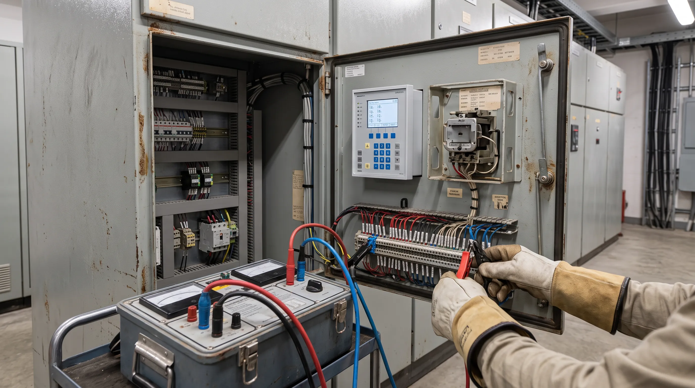
Quick Answer
A protection relay replacement succeeds or fails on five things matching: CT ratio and class, VT ratio, trip curves, communication protocol, and auxiliary supply. Miss one and the new relay misoperates even though it passed every bench test.
A protection relay replacement project rarely fails because of the relay itself. A new numerical relay passes every self-test the factory designed it to pass. What actually derails a protection relay replacement happens at the boundary: a current transformer sized for a relay retired decades ago, a trip curve that shares a name across two standards but not a shape, or a communication point list built for a protocol the old relay never spoke. None of that shows up on a datasheet comparison; it shows up during commissioning, or during the first real fault after the panel goes back into service, which is the expensive way to discover a mismatch.
Relay replacement compatibility starts at the CT, not the relay's settings menu: confirming CT and voltage transformer (VT) ratios and classes, carrying protection functions and trip curves across correctly, matching or converting the communication protocol, verifying auxiliary supply and wiring, and migrating settings through a proper coordination review rather than a straight copy. Skip any one of those and the replacement looks complete right up until it matters.
Why CT Ratio Is Where Most Relay Replacement Projects Go Wrong
Every overcurrent, earth fault, and differential function in a protection relay reads current through a current transformer, and the single most common error in a protection relay replacement is entering the wrong CT ratio into the new relay, or replacing the relay without verifying the CT it has inherited is the CT the original coordination study assumed.
CT ratio matching relay replacement work starts with reading the nameplate, not the drawing; panel drawings get revised when CTs are swapped for a higher-rated feeder, and as-built documentation does not always follow. A relay programmed with a 400:5 ratio sitting on a CT actually wound 600:5 reads every fault current roughly a third low, which either delays tripping past the coordination margin or, on a sensitive earth fault element, keeps it from picking up at all.
Ratio is only the first half of the check; class matters just as much. IEC 61869-2 defines protection classes by composite error: a 5P class CT is guaranteed within 5 percent composite error up to its accuracy limit factor, a 10P class within 10 percent. ANSI/IEEE C57.13 defines relaying accuracy differently, through C-class and K-class ratings stating the secondary terminal voltage a CT can deliver to a standard burden at 20 times rated current while holding 10 percent ratio error; a K-class CT adds a minimum knee-point voltage requirement a C-class CT does not. Differential protection has its own class entirely: PX class CTs, specified by knee-point voltage and winding resistance rather than a composite-error percentage, exist because differential schemes need near-identical CT behavior across every leg of the zone, or the scheme generates spurious operate current from mismatch alone.
A checklist that checks ratio and skips class is still incomplete. A numerical relay replacement reusing an old 10P10 metering-grade CT on a feeder that now needs differential protection has a problem no settings menu can fix, because the limitation sits in the current transformer.
VT Ratio and Burden: The Quieter Half of the Matching Problem
Voltage transformers get less attention than CTs during a protection relay replacement, mostly because fewer functions depend on them. Any relay doing directional overcurrent (ANSI device 67), distance protection (21), synchronism check (25), or voltage-restrained overcurrent needs a VT ratio matching what the relay is told, and a burden the VT can actually supply without its ratio and phase error growing beyond the class the coordination study assumed.
IEC 61869-3 governs voltage transformer accuracy classes the way IEC 61869-2 governs current transformers, with classes such as 0.5, 1, and 3P defined by voltage and phase error limits at specified burden points. A VT adequate for an older directional relay drawing a few VA can be marginal once the panel also carries a numerical relay's metering, a synchronizing panel, and a power quality meter on the same secondary winding. Total connected burden, not nameplate rating alone, determines whether the VT still meets its accuracy class in service, a budget worth checking with the same discipline behind our transformer testing and maintenance work.
On systems using open-delta or single-VT configurations, confirm the new relay's voltage connection setting matches the physical VT arrangement; a relay configured for a wye input wired to an open-delta VT set shows a real but wrong magnitude on at least one phase, an error that only surfaces once someone checks live readings during commissioning.
Trip Curves and Protection Function Compatibility
The original relay's job, whatever device numbers it covered under IEEE C37.2 (50/51 phase overcurrent, 50N/51N or 50G/51G earth fault, 87 differential, 67 directional), has to transfer completely to the new relay, and this is where a protection relay retrofit quietly becomes a protection relay cross reference exercise. Manufacturers publish cross-reference guides mapping discontinued models to current product lines, and those guides are a starting point, not a substitute for confirming every element the old relay performed is configured and tested on the new one; it is easy to migrate the primary overcurrent element and forget the panel also had a separate earth fault unit, because that function lived in a second case now physically gone.
Trip curve shape causes the most coordination surprises. IEC 60255-151 defines standard inverse, very inverse, and extremely inverse time-overcurrent curves on one set of equation constants; IEEE/ANSI C37.112 defines moderately inverse, very inverse, and extremely inverse curves on a different set. A curve labeled "very inverse" exists in both standards and does not produce the same trip time at the same multiple of pickup in either, because the underlying equations differ. Copying a curve name from an old settings sheet to a new relay's menu, without checking which standard family both use, is a documented way to shift an entire feeder's coordination margin without anyone changing a setting on purpose.
Differential protection (87) carries its own compatibility requirement beyond CT class: restraint and operate characteristics, harmonic restraint for inrush and overexcitation, and minimum pickup all have to be checked against the zone's actual fault current range, not assumed equivalent just because the function shares a name. A protection relay settings migration that treats "differential" as one interchangeable function across two relay generations is a shortcut a coordination study exists to catch before it reaches a live bus.
The Electromechanical to Numerical Relay Upgrade: What Actually Changes
Most protection relay replacement work on sites over twenty years old is an electromechanical relay to numerical relay upgrade, because that population is reaching protection relay obsolescence across entire switchrooms at once. Electromechanical relays from the 1970s through the 1990s are mechanically simple and reliable within their design life, but spare parts and calibration support keep thinning out, making numerical relay replacement the default path once an old relay reaches end of life rather than a like-for-like repair. Planning that cycle before the last spare part disappears belongs in an electrical maintenance and reliability program for aging switchgear.
Protection relay upgrade considerations go well beyond the enclosure. A numerical relay replaces a rack of single-function devices (one for phase overcurrent, one for earth fault, perhaps a lockout relay) with one microprocessor-based device running dozens of configurable elements, self-diagnostics, and a communication port the old panel never had. That consolidation also means its output contacts are usually lighter-duty than the heavy seal-in contacts they replace: a trip contact sized for a control circuit, not a high-inrush breaker trip coil directly, especially where control voltage (commonly 48 V DC) sits well below the trip coil's own supply (commonly 110 to 250 V DC). An interposing relay between the two is a normal part of a relay retrofit compatibility scope, not a sign something was specified wrong.
Protection relays are a different device class from the solid-state relays used for control-circuit switching, covered separately in our piece on solid-state relay sizing and failure modes; the two should never be confused when planning spares.
| What Changes | Electromechanical Relay | Numerical Relay |
|---|---|---|
| Protection functions per device | One function per case | Multiple functions, one case |
| Settings storage | Physical taps and dials | Digital, password-protected |
| Self-diagnostics | None | Continuous, with alarm output |
| Event/fault record | None, or external recorder | Built-in, time-stamped |
| Trip output contact duty | Heavy-duty seal-in contact | Lighter control-duty contact |
| Communication | None | Serial/Ethernet (IEC 61850, Modbus, DNP3) |
| Typical service life before obsolescence | 30 to 40-plus years mechanically | 15 to 20 years before platform end-of-life |
Communication Protocol: What the Relay Has to Say to the SCADA/RTU
If the original relay fed a SCADA system or an RTU, the communication protocol is part of a protection relay retrofit scope, not an afterthought for the controls team. Older electromechanical panels typically had no communication, just dry contacts wired to an RTU's digital inputs for trip and alarm indication; the first numerical relay on that feeder is often the first time it reports anything beyond on/off status. A numerical relay functions as an intelligent electronic device the same way a flow computer or RTU does, which is why protocol planning belongs with the same instrumentation and control engineering that specifies the architecture around it.
Where a numerical relay replaces an earlier one, the protocol question gets more specific. IEC 60870-5-103, the older companion standard for protection equipment interfacing, still runs on plenty of relays installed in the 2000s and early 2010s, and is not interchangeable with IEC 61850 without a gateway or a relay firmware option supporting both. IEC 61850 is itself not one protocol but a family: GOOSE for fast binary status and trip exchange, Sampled Values for streamed analog current and voltage, and MMS for client-server polling of settings and records; a relay claiming 61850 support may implement only part of that family.
Modbus RTU over RS-485, and DNP3 (serial or TCP/IP), remain the practical default where a site never moved to a full IEC 61850 substation LAN. A project that swaps protocols, say from a Modbus-only legacy relay to a DNP3-native one, needs the SCADA point list rebuilt and tested, not remapped by assumption, since DNP3 object and index numbering does not translate one-to-one from a Modbus register map. Confirm the team doing the panel swap also works through legacy RS-485 and RS-232 links correctly if serial wiring stays in place.
Auxiliary Supply, Terminals, and Wiring: The Part Nobody Budgets For
Auxiliary supply voltage is a simple check that still catches people out. IEC 60255-1 sets the common requirements protection relays are tested against, and most numerical relays ship with a rated DC input covering a defined nominal voltage and range, commonly a low-voltage variant around 24 to 48 V DC and a higher-voltage variant spanning 110 to 250 V DC. A relay ordered for the wrong range either will not power up, or runs inside a window far enough from its design center that internal supervision starts logging warnings nobody expected on day one.
Terminal and wiring compatibility is the unglamorous part of a relay replacement checklist that decides how much of the commissioning window gets eaten by panel work instead of testing. Electromechanical relays typically used larger ring-and-stud or barrier-strip terminals; numerical relays mostly use smaller plug-in or screw terminal blocks, which rarely line up with the original gland and rail layout without an adapter plate or partial rewire. Budget that work explicitly rather than discovering it during the outage window, since almost no retrofit lands on an exact physical match; it is work our electrical engineering team scopes before an outage, not during one. CT and VT secondary wiring deserves its own check too: confirm shorting terminal blocks or test switches exist ahead of the relay's CT inputs, since open-circuiting a live CT secondary is a genuine hazard, not a procedural formality.
Protection Settings Migration and the Coordination Study You Cannot Skip
Protection relay settings migration is not a copy-paste exercise, even when the new relay's menu looks similar to the old one. Settings on the retired relay reflect the system as it existed when last reviewed, which on a site with twenty- or thirty-year-old electromechanical relays is frequently a system that has since had transformers re-rated, feeders added, or generation connected that the original coordination study never saw.
A relay retrofit compatibility review has to re-run the protection coordination study, not just re-enter the old numbers. Curve family differences, covered above, mean an identical pickup and time dial setting on two platforms can produce a materially different trip time, and numerical relays expose settings ranges and minimum time delays that do not match an electromechanical relay's mechanical limits, so a setting that was "as fast as the old relay could go" may now have margin available, or may need a delay the old relay physically could not provide. Functions the old relay never had, such as negative-sequence protection or breaker failure, default to something on day one, and that default is not automatically coordinated with the rest of the scheme.
This is the stage where a protection relay replacement project either stays a genuine reliability upgrade or quietly becomes a liability, because mis-coordinated protection does not announce itself. It sits correctly configured-looking in the relay's settings display until the fault that exposes the gap, usually at the worst possible time to find it. Running the coordination study as part of the retrofit project, not as a formality after settings are entered, is the difference between those outcomes, and it is exactly the work covered under a dedicated power system audit and protection coordination review.
Real-World Scenario: A Cement Plant's Kiln Switchgear Retrofit
A cement plant running two kiln lines had an 11 kV switchboard feeding the induced draft (ID) fan motors through electromechanical overcurrent and earth fault relays installed in the late 1980s. The relays still worked mechanically, but spare induction-disc elements had become impossible to source, and the reliability team scheduled a protection relay replacement across both ID fan feeders during a planned kiln outage.
The replacement relays, numerical units from a current product line, were specified, programmed from the original settings sheet, and installed ahead of the outage to save commissioning time. During pre-energization secondary injection testing, the pickup current the relay actually operated at did not match the calculated value, off by close to a third. The panel drawings listed the ID fan feeder CTs as 400:5. The CTs physically installed, confirmed from the stamped nameplate once the panel was opened, were 600:5, changed out during a fan motor upsize roughly a decade earlier without the single-line diagram ever being revised.
Relay replacement compatibility work caught this before the fan went back into service, because secondary injection testing checks the relay's actual response against calculated values rather than trusting the settings sheet. Had the fan been re-energized on the uncorrected ratio, the overcurrent element would have picked up well after intended relative to actual primary current, eating directly into the margin the coordination study assumed between the ID fan feeder and the upstream incomer protection.
A settings sheet tells you what someone believed was installed. Secondary injection testing tells you what is actually there, and a protection relay replacement is not finished until those two things have been proven to agree.
The fix was straightforward: re-ratio the relay's CT setting to 600:5, recheck the coordination margin, and re-run the test. The expensive part was not the correction; it was how close the plant came to commissioning a mismatched protection scheme on a feeder guarding a fan large enough to shut down an entire kiln line if it failed uncontained.
Re-Commissioning: Primary and Secondary Injection Before You Trust the New Relay
No protection relay replacement is complete until the new relay has been tested the way the old one was last proven correct: with current and voltage actually injected into it, not verified by menu inspection alone. Secondary injection testing feeds test currents and voltages directly into the relay's terminals from a protection test set, isolating the relay itself to confirm pickup values, time delays, and curve shape against the calculated settings. It never touches the CTs, VTs, wiring, or breaker trip circuit, which is why it is not sufficient on its own.
Primary injection testing pushes current through the actual primary conductor and the real CT, proving CT ratio, CT wiring polarity, and the full trip path from relay to breaker trip coil end to end. It needs larger test equipment and usually takes the feeder out of service, which is why most sites reserve it for commissioning and major CT or wiring changes rather than routine testing. For a CT ratio matching relay replacement where the as-built ratio is in any doubt, as the cement plant scenario above shows, primary injection, or at minimum a confirmed nameplate check paired with secondary injection, is not optional.
A short protection relay compatibility checklist for re-commissioning holds up across most sites: confirm CT and VT ratios against nameplate, not drawing; secondary-inject every enabled function against the coordinated settings; primary-inject where CT wiring or ratio changed; verify trip and alarm contacts hit the correct breaker and annunciator points; and confirm communication points report correctly to SCADA before the relay is left unattended. None of these are optional extras. They are the difference between a relay that passed a bench test and one actually trusted to protect the feeder it sits on.
Getting there, a fully tested, coordinated protection relay replacement rather than a relay that merely powers up, benefits from being scoped end to end rather than handled as a parts swap. Working through CT and VT verification, protocol planning, and settings migration together is what turns a legacy protection relay replacement from a gamble on commissioning day into a planned upgrade.
Frequently Asked Questions
What must match when replacing industrial protection relays?
CT ratio and accuracy class, VT ratio and burden, the protection functions and trip curves the original relay performed, the communication protocol if the relay feeds a SCADA or RTU, and the auxiliary supply voltage all have to match or be deliberately converted. Terminal and wiring compatibility, and a re-run protection coordination study covering the migrated settings, complete the list. Missing any one of these is what turns a protection relay replacement into a nuisance-trip or under-protection problem after commissioning.
What is CT ratio matching and why does it matter?
CT ratio matching means confirming the current transformer's actual physical ratio, read from its nameplate rather than the panel drawing, matches what is programmed into the new relay. A mismatch makes every protection element read current incorrectly: a relay programmed for a lower ratio than installed reads faults low and can under-reach or fail to clear a fault inside the coordination margin the study assumed. It is the single most common error in a protection relay replacement because panel drawings are rarely updated when a CT is swapped for an unrelated reason, such as a motor upsize.
Can an electromechanical relay be replaced directly with a numerical relay?
Yes, and an electromechanical relay to numerical relay upgrade is the most common form of protection relay replacement today, since spare parts and calibration support for older electromechanical devices keep thinning out across the industry. The relay itself swaps directly, but the CT and VT circuits, trip output wiring, and auxiliary supply almost always need verification or adapter work, because a numerical relay's terminal layout, contact ratings, and burden requirements differ from the device it replaces. Treat it as a full retrofit project, not a one-for-one swap, even though the new relay usually fits the same panel cutout.
What happens to existing protection settings during a relay retrofit?
Settings do not transfer as raw numbers; they have to be migrated through a protection coordination study, because curve families differ between standards, IEC 60255-151 versus IEEE/ANSI C37.112, and a numerically identical setting can produce a different trip time on the new platform. Protection relay settings migration also has to account for any system changes since the original study, such as re-rated transformers or added feeders, that the retired relay's settings never reflected. The new settings are only proven correct once they have been verified through secondary injection testing, and through primary injection as well wherever CT wiring changed.
Related products
Components from our catalogue relevant to this article — request a quote for availability, lead time and pricing.
/GHB3030-GR1 Eaton.webp "Eaton GHB3030-GR1 Eaton | Eaton GHB Circuit Breaker")
GHB3030-GR1 Eaton
Eaton GHB Circuit Breaker
/009737 Eaton - ZW7-240.webp "Eaton 009737 Eaton - ZW7-240 | Eaton Overload Relay")
009737 Eaton - ZW7-240
Eaton Overload Relay
/004991 Eaton - ZW7-125.webp "Eaton 004991 Eaton - ZW7-125 | Eaton ZW7 Overload Relay")
004991 Eaton - ZW7-125
Eaton ZW7 Overload Relay
/TC625 AF100 ABB - Coaxial Modem 3BSE002224R1.png "ABB TC625 AF100 ABB - Coaxial Modem 3BSE002224R1 | Coaxial modem TC625 AF100")
TC625 AF100 ABB - Coaxial Modem 3BSE002224R1
Coaxial modem TC625 AF100