
Selecting a Medium Voltage Motor: The Specification Decisions That Actually Matter

Quick Answer
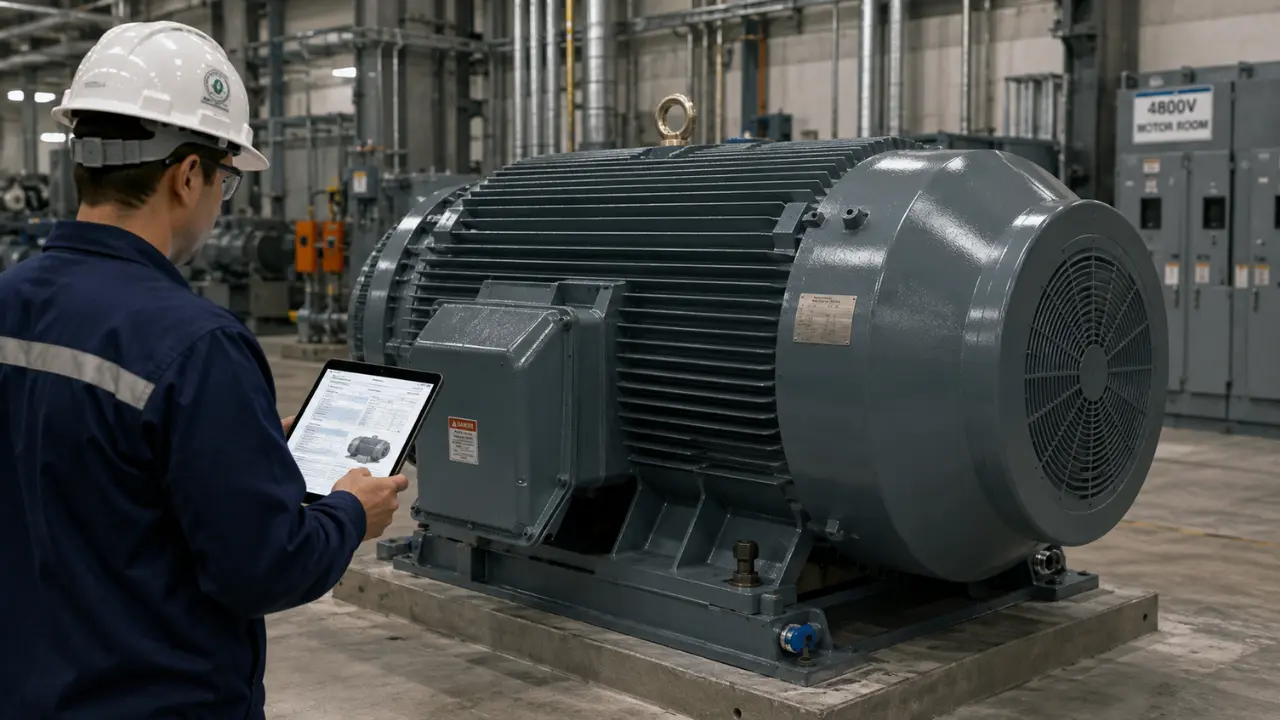
A medium voltage motor covers 2,300 V to 15,000 V under IEEE/NEMA definitions, and getting the spec right means matching insulation class, starting method, bearing type, and enclosure to the actual load and site conditions, not copying the outgoing nameplate.
Specifying a medium voltage motor is not the same exercise as specifying a low voltage motor with a bigger nameplate. The voltage class changes the insulation system, the starting method, the bearing design, the acceptance testing, and the lead time all at once, and a mistake in any one of those decisions tends to show up as a failure eighteen months after startup, not a rejection at commissioning. If you're writing the spec for a new compressor train, a large pump, or a mill drive, the decisions below determine whether the motor runs for twenty years or gets pulled for a rewind inside of three.
A medium voltage motor spec is not one decision. It's roughly a dozen decisions that all have to agree with each other.
Where Medium Voltage Actually Starts
IEEE and NEMA define medium voltage as the range from 2,300 V to 15,000 V. Below that, you're in low voltage territory (600 V and under in North American practice, with 690 V common internationally). Above 15 kV, you're into high voltage motor territory, a smaller and more specialized market. This piece sits inside that 2.3 kV to 15 kV band, with 2.3 kV, 4.16 kV, and 6.6 kV covering most installed medium voltage motors worldwide.
The decision to move to medium voltage is really a current decision, not a voltage decision. As horsepower climbs, full-load current at low voltage climbs with it, and at some point the cable sizes, breaker frames, and switchgear needed to carry that current get expensive and physically unwieldy. Most plants cross that line somewhere between 250 and 500 HP, though the exact threshold depends on run length, ambient conditions, and what voltage the utility feed already delivers. A 400 HP motor fed from a 480 V bus 300 feet from the switchgear is a legitimate low voltage application. The same motor 3,000 feet out, or paired with three others on one feeder, starts looking like a medium voltage motor even before horsepower forces the issue.
There's real commercial weight behind that decision too: Intel Market Research pegs the global medium voltage motors market at USD 6.2 billion in 2024, growing at roughly 4.2 percent annually through 2032 on power generation, oil and gas, water and wastewater, and mining demand for large compressor, pump, and fan drives. That demand pressure on the medium voltage motors market is part of the lead time story covered later in this piece.
Starting Method Drives the Motor Control Design
The starting method is the first fork in the road. It decides what has to sit inside the medium voltage motor control center itself: contactor and vacuum interrupter ratings, bypass provisions, and protection relay classes, plus switchgear rating and cable sizing downstream.
Across-the-Line Starting
Direct-on-line starting at medium voltage is simple and cheap, but the inrush is brutal: typically 5 to 7 times full-load current, arriving as a step change the instant the contactor closes. On a large motor, that inrush can dip voltage across the whole plant bus, enough to drop out contactors, upset VFDs on adjacent feeders, or flicker lighting badly enough to draw complaints. Torque follows current in an induction motor, so across-the-line starting also delivers a torque spike at breakaway that the coupling and gearbox must absorb. For motors under roughly 1,000 HP on a stiff utility bus, it's often still the right call: the cheapest medium voltage motor control option, nothing extra to maintain.
Reduced-Voltage and VFD Starting
Autotransformer and reactor starters knock the applied voltage down during the start, typically to 50 to 80 percent of line voltage, cutting inrush roughly in proportion but cutting starting torque with the square of that ratio. That penalty matters: a centrifugal pump with low breakaway torque tolerates it fine, while a loaded conveyor or positive-displacement compressor may stall before reaching transition speed. These starters are more complex than a simple contactor, with more failure points, but remain proven where inrush needs controlling and a full drive isn't justified.
A medium voltage VFD eliminates the inrush problem entirely by ramping frequency and voltage together from zero, adding continuous speed control as a byproduct. That's the right call whenever the process actually needs variable speed, the same logic behind the VFD vs soft starter decision at low voltage: don't buy variable speed capability for a fixed-speed load. At medium voltage, the drive becomes a major line item inside the motor control center, with cell-based or multilevel topologies, harmonic mitigation, and dedicated cooling. Our medium voltage motor VFD panel selection checklist covers drive topology, bypass provisions, and panel integration in more depth than fits here.
Insulation System and Thermal Rating
Medium voltage motors are almost always form-wound rather than random-wound: the stator coils are pre-formed, taped with a mica-based insulation system, and inserted into the slots as rigid assemblies rather than wound in place. That construction lets the winding survive line-to-line and line-to-ground voltage stress that would puncture a random-wound low voltage insulation system in short order.
NEMA MG 1 defines insulation classes by the maximum winding temperature the system can sustain continuously: Class B at 130°C, Class F at 155°C, and Class H at 180°C, each built from a 40°C reference ambient plus an allowable rise plus a hot-spot margin. Class F is the de facto standard for medium voltage motors today, but most manufacturers design the winding to run at a Class B temperature rise while carrying a Class F system, banking the difference as thermal margin rather than pushing more output from the same frame. That margin is cheap insurance. Insulation life follows a roughly Arrhenius relationship with temperature, and the commonly cited rule of thumb, sometimes called Montsinger's rule, holds that insulation life is cut in half for every 10°C of sustained overtemperature. A motor running 15 to 20°C hotter than necessary because someone specified for headroom on paper isn't a paper problem. It's a five-to-ten-year life reduction that shows up as an unplanned rewind.
Enclosure Type: TEFC, WP I/WP II, and Explosion-Proof Variants
Enclosure selection has to match the actual site environment, not the environment on the equipment list. Totally enclosed fan-cooled (TEFC) construction is the default for indoor and moderately dirty environments, sealing the internals from surrounding air while an external fan pushes ambient air across finned housing to reject heat. Weather-Protected Type I (WP I) allows ventilating air through the machine with basic screening against solid objects; Weather-Protected Type II (WP II) adds baffled ventilation paths so wind-driven rain, snow, and airborne particles get thrown clear before reaching the windings, which is why WP II is standard on large outdoor MV motors driving pumps, fans, and compressors that can't be housed indoors.
Hazardous locations complicate the picture. Explosion-proof (Ex d) construction, common on smaller low voltage motors in Class I Division 1 or Zone 1 areas, becomes impractical at large MV frame sizes: an enclosure heavy enough to contain an internal explosion gets prohibitively heavy and expensive at that size. Purge and pressurization (Ex p, under NFPA 496 and IEC 60079-2) is the more common answer instead, keeping the flammable atmosphere out with continuous positive-pressure air or inert gas rather than trying to contain an ignition inside. Confirm the area classification against IEC 60079 or NEC Articles 500/505, plus ATEX or IECEx certification where applicable, before enclosure type is locked into the spec.
Bearing Type: Sleeve vs Anti-Friction on Large Frames
Bearing selection is where a lot of medium voltage motor specs go wrong, usually by defaulting to the vendor's standard offering rather than matching the bearing to frame and duty. Anti-friction (rolling element) bearings are simpler, cheaper, and need no external lubrication, a reasonable choice up to roughly 1,500 to 2,000 HP, particularly at standard two- and four-pole speeds. Above that range, most manufacturers move to sleeve bearings, and it isn't primarily a load rating decision. It's a rotordynamics decision: large, long rotors at higher shaft speeds behave as flexible rotors rather than rigid ones, and sleeve bearings provide the oil-film damping needed to control shaft vibration through the machine's critical speeds. A rolling element bearing offers essentially no damping, fine on a short, stiff low-HP rotor and a liability on a long flexible one.
Sleeve bearings bring their own obligations: a reliable oil supply, either self-lubricated rings on smaller frames or forced lubrication with pumps, coolers, and filtration on the largest machines, commissioned and monitored, not just installed. Skipping those auxiliary systems is exactly the kind of mistake that shows up in the field scenario below.
Service Factor and Efficiency Class
NEMA MG 1 permits a 1.15 service factor on many low voltage motors: continuous operation at 15 percent over nameplate load without exceeding the insulation rating. Medium voltage motors are typically specified at 1.0 service factor instead, since that thermal margin is expensive to build into a form-wound winding and a large iron core. Most process engineers would rather size the motor correctly for the actual load than pay for margin they don't plan to use.
Efficiency labeling is a separate conversation at medium voltage. IEC 60034-30-1's IE efficiency classes (IE1 through IE4) apply to low voltage motors; there's no equivalent mandatory scheme covering the MV range. That doesn't mean efficiency doesn't matter, it means it isn't reduced to a label. Core losses, stray load losses, windage and friction still cost real money over a multi-year duty cycle, worth interrogating on the manufacturer's measured test data rather than assuming a name-brand motor is automatically efficient.
Altitude and Ambient Temperature Derating
NEMA MG 1's standard service conditions assume 1,000 meters altitude and 40°C maximum ambient. Push past either limit and thermal capacity drops, since thinner air carries less heat away and ambient temperature sits closer to the insulation's ceiling. The rule of thumb is roughly 3 percent output derate per 500 meters above 1,000 meters, confirmed against the manufacturer's certified curve, not a generic table; both effects compound on desert and high-plateau sites, a common miss on international projects: a motor sized for sea level ships to a 2,200-meter site at 45°C ambient and runs hot for good because nobody re-ran the sizing.
Vibration and Noise Standards
Vibration acceptance for medium voltage motors is set against ISO 20816-3, which establishes vibration severity zones, A through D, from newly commissioned condition through levels requiring immediate remedial action, for industrial machinery above 15 kW. Petrochemical specs built on API 541 and API 546 typically call for tighter limits than the general ISO 20816-3 baseline, reflecting low tolerance for downtime on critical process trains. Noise limits fall under NEMA MG 1 Part 9 or IEC 60034-9, and matter beyond hearing conservation: elevated noise is often an early indicator of a bearing or cooling fan problem, and many sites carry permit-driven sound limits at the property line that a large motor can push against.
Why Acceptance Testing Looks Different at Medium Voltage
Medium voltage motor commissioning and factory acceptance testing carry more weight than low voltage tests, because the failure modes screened for are different and the cost of missing one is higher. Insulation resistance and polarization index testing under IEEE 43 remain baseline checks, but form-wound MV windings also get surge comparison testing under IEEE 522 to catch turn-to-turn weaknesses a megohm reading won't reveal, plus offline partial discharge testing to catch voids or delamination in the groundwall insulation before it progresses to a fault. High-potential testing is its own decision point: IEEE 95 covers DC methodology, but many current specs favor AC or very low frequency (VLF) withstand testing under IEEE 433 instead, since the stress distribution more closely matches how the winding sees voltage in service and DC can leave trapped space charge in some insulation systems. None of this is optional paperwork; it's the difference between finding a defect on the factory floor and finding it as an unplanned trip six months in. Our companion piece on motor testing methods and what each test actually catches covers each test and the failure mode it's designed to catch.
A Real-World Scenario: The Bearing and Heater Mistake
The Setup
A sugar processing plant in a humid coastal region replaced an aging 1,250 HP, 4.16 kV motor driving a mill train with a new unit sourced through a low-bid process. The replacement spec called out a standard anti-friction bearing matching the outgoing motor's nameplate, and space heaters were listed on the datasheet but value-engineered out of the purchase order to hit a budget number, on the logic that a continuously running motor generates its own heat anyway.
What Went Wrong
The motor ran fine through the crushing season. During the off-season shutdown, it sat idle for six weeks in a mill house with no climate control and humidity regularly above 85 percent. Without space heaters keeping the windings and bearing housings a few degrees above ambient, moisture condensed inside the motor overnight as temperatures cycled, settling in the bearing housing and washing contamination into the rolling elements. When the mill restarted, the motor ran eleven days before a bearing failure took it offline, with clear evidence of water-contaminated grease and early-stage fretting corrosion on the raceway.
The Fix
The replacement went back in with space heaters wired into the plant's shutdown sequence so they energize automatically whenever the motor stops, plus a bearing arrangement re-evaluated against the mill's actual duty cycle rather than copied from the old nameplate. The mechanical case for anti-friction versus sleeve bearings at 1,250 HP was genuinely close either way, but the missing space heaters were not close at all. They're inexpensive and standard on most manufacturers' medium voltage motor offerings, and cutting them to save a few hundred dollars on a six-figure motor looks fine on a spreadsheet and terrible in a maintenance report.
Space heaters cost less than a single bearing replacement. Leaving them off a motor that sits idle in a humid plant isn't a savings. It's a deferred failure.
Lead Time and Procurement Realities
Large medium voltage motors are not shelf items: custom-wound stators, large iron castings, and forced-lubrication sleeve bearing assemblies push lead times to 20 to 50 weeks or more before backlog even enters the picture, and demand across the medium voltage motors market, from data center power infrastructure to LNG, petrochemical, and mining electrification, keeps that range climbing and several manufacturers' order books full enough that lead time, not price, is often the deciding factor in vendor selection.
Lock the spec early. Confirm bearing type, insulation system, and testing requirements before releasing the purchase order to avoid a change order that adds months to an already long lead time. The same applies to the medium voltage motor control center the motor feeds into: a motor built without a confirmed starter or drive bucket lead time sits in a warehouse waiting on its own control gear. An electrical engineering partner who tracks actual manufacturer capacity, not a stale catalog figure, is worth it on any critical-path project, the same scrutiny worth applying to high voltage transformer procurement.
Spec Checklist: What to Lock Before You Issue the PO
| Spec Item | Key Question | Typical Reference |
|---|---|---|
| Voltage class | Does load and cable run justify 2.3-15 kV vs. staying low voltage? | IEEE/NEMA MV definition |
| Starting method | Across-the-line, reduced-voltage, or VFD, based on bus stiffness and load torque | Utility/plant fault study |
| Insulation system | Class F system, Class B temperature rise for margin | NEMA MG 1 |
| Enclosure type | TEFC, WP I/II, or Ex p for hazardous locations | IEC 60079, NEC 500/505 |
| Bearing type | Anti-friction under ~1,500-2,000 HP; sleeve above | Manufacturer rotor study |
| Service factor | 1.0 SF standard at MV; confirm actual load margin | NEMA MG 1 |
| Efficiency | Measured test data requested; no mandatory IE class at MV | IEC 60034-30-1 (LV only) |
| Altitude/ambient | Derating confirmed against actual site conditions | NEMA MG 1, manufacturer curve |
| Vibration/noise | Severity zone and limits set against duty criticality | ISO 20816-3, API 541/546 |
| Acceptance testing | PI, surge test, hipot method, partial discharge scope | IEEE 43, 522, 433/95 |
| Space heaters | Included, wired into shutdown sequence | Manufacturer standard |
| Lead time | Confirmed build slot, not catalog estimate | Manufacturer/distributor |
Getting the Spec Right the First Time
None of these decisions exist in isolation. The starting method sets the insulation stress the winding sees on every start. The bearing type sets what the vibration acceptance criteria should look like. Site altitude and ambient conditions decide whether the service factor on paper is real margin or already spent. A spec that gets each of these right individually but never checks them against each other still has a gap in it.
If you're building the electrical and mechanical spec for a new medium voltage motor, sourcing a replacement unit against a tight outage window, or working out the acceptance testing plan before the motor lands on site, Techno Control Corp's engineering team handles this with plants and OEMs regularly. Browse our products catalog for the equipment side of the spec, or contact us to walk through your application and get a sourcing timeline that reflects what's actually available.
Related products
Components from our catalogue relevant to this article — request a quote for availability, lead time and pricing.
/010005 Eaton - DILEM-10(24V50HZ).webp "Eaton 010005 Eaton - DILEM-10(24V50HZ) | Eaton DILEM contactor")
010005 Eaton - DILEM-10(24V50HZ)
Eaton DILEM contactor
/Siemens 1LE1001-1AB42-2KA4-Induction Motor.webp "Siemens 1LE1001-1AB42-2KA4 Siemens - Induction Motor | Low-voltage three-phase induction motor")
1LE1001-1AB42-2KA4 Siemens - Induction Motor
Low-voltage three-phase induction motor
/Siemens 1LE1001-1BB22-2FA4-SIMOTICS GP motor.webp "Siemens 1LE1001-1BB22-2FA4 Siemens - SIMOTICS GP Motor | SIMOTICS GP general-purpose motor")
1LE1001-1BB22-2FA4 Siemens - SIMOTICS GP Motor
SIMOTICS GP general-purpose motor
/Siemens 1LE1003-1AA42-2FA4-Low voltage motor.webp "Siemens 1LE1003-1AA42-2FA4 Siemens - Low Voltage Motor | Low-voltage three-phase motor")
1LE1003-1AA42-2FA4 Siemens - Low Voltage Motor
Low-voltage three-phase motor