
Digital Twin in Manufacturing: What It Actually Models, and What It Does Not

Quick Answer
A digital twin in manufacturing is only a real twin if it carries a live bidirectional data link and a physics or behavioural model. Most of what is sold under the name is a 3D model or a dashboard, and neither will predict a bearing failure.
A vendor demo I sat through last year opened with a rotating 3D render of a filling line, live throughput counters floating above each machine. Good software. It was not a digital twin in manufacturing in any sense that would survive an engineering review, and the plant that bought it took eighteen months to work that out.
The term now covers almost anything with a screen behind it: a CAD assembly, a historian dashboard with better typography, a game-engine scene fed by an OPC UA subscription. None will tell you that the number four boiler feed pump has an inner-race defect that takes it offline in six weeks, usually what the plant thought it was buying.
Two things separate a twin from a picture: a live bidirectional data link, and a model that computes something no sensor on the asset measures directly. Remove either and you have a visualisation.
If the model cannot tell you something no instrument on that asset is measuring, it is a dashboard with perspective.
What Is a Digital Twin in Manufacturing?
A digital twin in manufacturing is a virtual representation of a physical asset or process, synchronised with that asset at a defined rate and fidelity, containing a physics-based, empirical or behavioural model that estimates states the instrumentation does not measure directly.
The Digital Twin Consortium's 2020 definition is the one most vendors quote and fewest meet: a digital twin is "a virtual representation of real-world entities and processes, synchronized at a specified frequency and fidelity." Two words carry the weight. Synchronized rules out a model refreshed from a spreadsheet once a quarter. Specified means somebody must name the rate, and if nobody can, nobody has designed a twin yet.
ISO 23247, Automation systems and integration: Digital twin framework for manufacturing, published Parts 1 to 4 in October 2021: general principles, reference architecture, digital representation of manufacturing elements, information exchange. Parts 5 and 6 followed in 2026. Part 2 separates four things vendors blur: the observable manufacturing element, the data collection and device control entity, the core entity holding the models, and the user entity consuming their output.
That split has commercial teeth. Ask which entities a quoted price covers. Most quotes I have reviewed deliver the user entity and a thin slice of data collection, then assume the plant owns the instrumentation, the network, the time base and the models: the expensive parts.
The Four Levels, Graded Honestly
Arguments about whether something counts as a digital twin in manufacturing dissolve once you grade it.
Level 1: The Descriptive 3D Model
A geometrically accurate model, from laser scan or original CAD, with no live data. A drawing that rotates. Useful for clash detection, maintenance access planning and contractor briefing. It predicts nothing.
Level 2: The Connected Asset Twin
Level 1 plus live tags bound to the right objects. Most of what is sold as a twin sits here. It answers "what is happening now" faster than a conventional SCADA and PLC architecture does. It still contains no model: delete every tag and the geometry is unchanged. Nothing is computed.
Level 3: The Simulation Digital Twin
Here a model enters. A simulation digital twin runs equations alongside the asset: a thermal network, a hydraulic curve, a motor equivalent circuit. The value is the residual, the gap between what the model says should be happening and what the instruments report. A pump drawing 8 percent more shaft power than predicted at the measured flow and head is saying something about internal clearances no single sensor reading contains. Level 3 is where projects stall: a simulation digital twin must be calibrated against the specific machine, not the catalogue machine, then recalibrated after every overhaul.
Level 4: The Predictive or Autonomous Twin
The model runs ahead of the asset, projects forward under assumed load, and in the autonomous case writes setpoints back through the control system. This is the only level that earns the word "predictive", and the only one where the bidirectional link is mandatory. A write path into a control system is a cybersecurity commitment under IEC 62443, and often a functional-safety commitment too under IEC 61508, 61511 or 62061, neither approved from a slide. Plenty of useful twins stay read-only, handing a recommendation to an operator: legitimate, but not autonomous, and not worth autonomous pricing.
| Level | Live data link | Model inside | Question it answers | Where it fails |
|---|---|---|---|---|
| 1. Descriptive 3D model | None | None | Where is it, how do I reach it | Sold as if predictive |
| 2. Connected asset twin | One-way read | None | What is happening now | Mistaken for Level 3 |
| 3. Simulation digital twin | One-way, high rate | Physics or empirical | Is it behaving as designed | Never recalibrated after overhaul |
| 4. Predictive twin | Bidirectional | Physics plus degradation | What happens next | Sample rate and time sync too poor |
Levels 1 and 2 are bought. Levels 3 and 4 are built, calibrated and maintained. Pricing rarely reflects the difference.
Digital Twin vs Simulation: The Difference Is the Direction of the Data
A simulation is a model fed with assumptions. A twin is a model fed with measurements from one specific asset, continuously, that feeds something back into how it is run.
Run a CFD study of a mixing vessel before it is built and you have a simulation. Bind the same solver to the live jacket temperature, agitator speed and feed flow of vessel TK-204 and you have a twin of TK-204. Same mathematics, different data source, and a maintenance obligation the simulation never had.
The practical test during a demo: pull the network cable. If the numbers freeze while the model runs on assumed inputs, it is a simulation wearing a live skin. A real time digital twin knows when it has lost synchronisation and says so.
What Data Does a Digital Twin Need?
A digital twin needs data sampled at a rate matched to the physics it models, tags unambiguously bound to one asset, a single time base across every source, and for Level 4 an audited write path to the controller. Most stalled digital twin manufacturing projects failed at one of those four, not at the modelling.
Sample Rate: The Prerequisite Nobody Quotes
This is what quietly kills digital twin predictive maintenance claims. Take rolling-element bearing defects, the failure mode most often promised. BPFO, BPFI and BSF fall roughly between three and twelve times shaft speed, so on a four-pole 50 Hz motor near 1,480 rpm they sit between roughly 75 Hz and 300 Hz. FTF, the cage frequency, is the exception: always sub-synchronous, roughly 0.35 to 0.48 times shaft speed, about 10 Hz here. None of those frequencies is where early damage shows up. Incipient defects appear as low-energy impacts ringing structural resonances in the 2 kHz to 20 kHz band, which is why envelope demodulation exists and credible analysis acquires raw waveform in the tens of kilohertz.
Now consider what most plants have: a 15-minute average of an overall RMS velocity value, written to the historian through a compression algorithm tuned to save disc space. One sample every 900 seconds. Nyquist alone caps what can be resolved well under a millihertz, and averaging has already destroyed the impulsive energy carrying the diagnosis. A twin fed from that tag cannot detect an incipient bearing fault, not merely detect it late. That is a matter of signal processing, not model quality.
The logic runs the other way too. A transformer thermal model has time constants of tens of minutes; feeding it at 10 Hz burns bandwidth without adding accuracy. Match the rate to the physics. That decision belongs to whoever specifies the field instrumentation and control loops, because it usually means new sensors, not new software.
Tag Naming and Asset Structure
A twin binds models to assets, so assets must be identifiable. Where a historian has grown organically for fifteen years, they usually are not: the same pump appears as P204, PMP_204A, Area3.Pump204 and FIC-204.PV depending on which integrator was on site that year, two of them pointing at equipment replaced in 2019.
IEC 62264 (ISA-95) gives the hierarchy worth imposing first: enterprise, site, area, work centre or line, work unit; the discipline is choosing a depth and applying it everywhere. IEC 63278-1:2023 goes further with the Asset Administration Shell, whose metamodel serialises to JSON, XML, AutomationML or an OPC UA information model: the most durable asset description available when it must outlive a change of software vendor. Budget for it. Historian cleanup routinely consumes more effort than the twin itself, and skipping it binds models to the wrong machine.
Time Synchronisation: NTP Is Not Good Enough for Electrical Models
Where a twin fuses data from several sources (drive, protection relay, power meter, vibration collector, PLC), timestamps must agree to a tolerance set by the fastest phenomenon modelled.
NTP over a plant LAN realistically holds a few milliseconds, worse across firewalls and virtualised servers. For a thermal model, irrelevant. For anything phase-dependent, fatal: at 50 Hz one cycle is 20 ms, so 1 ms of skew between a voltage and a current source is 18 electrical degrees. A twin estimating torque, power factor or shaft power from separately timestamped V and I is wrong before anyone questions an equation.
IEEE 1588-2019 (PTP v2.1), with hardware timestamping and boundary or transparent clocks in the switches, holds sub-microsecond synchronisation across an industrial Ethernet segment. Retrofitting it means replacing switches, so it belongs in the network design, not the recovery plan.
Digital Twin Examples From Assets We Work On Every Week
Three digital twin examples from equipment found on almost every site make the argument concrete.
A Motor and Its Drive
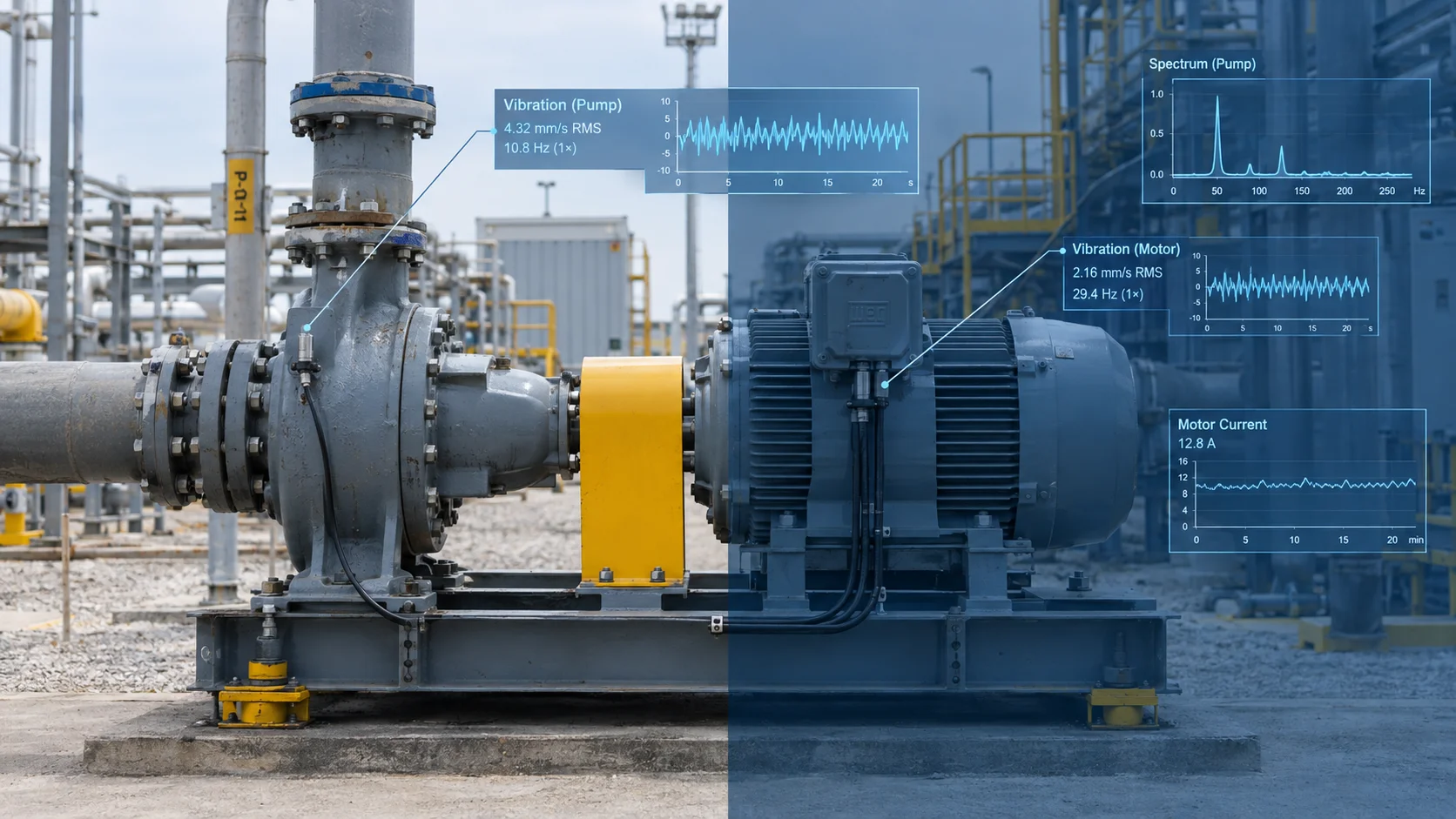
The most underrated twin in most plants is already installed and nobody calls it one. A vector-control drive maintains an internal motor model (stator resistance, rotor time constant, magnetising inductance, estimated flux vector, winding thermal model) and updates it every few hundred microseconds to control torque. It is a real time digital twin of the motor in everything but branding.
Two consequences. The autotune at commissioning is a model identification step, not a formality, and skipping it degrades every estimate the drive makes afterwards. And its estimated torque, speed and thermal-model output already travel over PROFINET or EtherNet/IP, far cheaper to read than to re-derive. Before buying a motor twin, find out what the variable frequency drive already knows. What no drive sees is insulation condition, which still needs the tests in our guide to motor testing methods and what each one catches.
A Centrifugal Pump
A pump is the clearest Level 3 case in most plants: the physics behaves, the economics are obvious. Model the manufacturer's head-flow and efficiency curves, corrected for installed impeller diameter and actual speed through the affinity laws, then compare predicted shaft power against measured electrical power corrected for motor and drive efficiency. A sustained positive residual at constant duty means hydraulic degradation: impeller wear, wear-ring clearance, fouling.
The trap is the inputs. Many pump twins run on a flow value calculated from pressure and the pump curve, then use it to detect deviation from that same curve. That is circular, and it will report perfect health forever. A pump twin needs independent flow measurement and suction conditions, because NPSH available collapses as liquid temperature rises. A twin modelling head without NPSH margin misses cavitation entirely, which is not a corner case on Gulf sites where suction temperatures swing seasonally.
A Power Transformer
Transformers have the best-standardised twin in industry, and it predates the vocabulary by decades. IEC 60076-7:2018, the loading guide for mineral-oil-immersed power transformers, specifies thermal models computing top-oil and winding hot-spot temperature from load current and ambient. Feed it live data and you get hot-spot temperature, which almost nobody measures directly, plus a relative ageing rate that for non-thermally-upgraded paper doubles for roughly every 6 K above the 98 °C hot-spot reference.
Two failure modes recur. Ambient input is often taken from a weather feed or a shaded sensor rather than the transformer's own yard, which in a 50 °C Gulf summer understates hot-spot by a margin that matters to insulation life. And cooling-stage status is frequently not modelled, so the twin assumes ONAF while a failed fan bank has silently returned the unit to ONAN. Both are instrumentation problems. A thermal twin says nothing about incipient internal faults either, which is why it complements rather than replaces dissolved gas analysis.
A Real-World Scenario: The Boiler Feed Pump the Twin Never Saw
The Setup
A fertiliser complex on the Arabian Gulf coast commissioned a twin across its utilities area as part of a wider Industry 4.0 programme. Scope included three 6.6 kV, 1,250 kW boiler feed pumps, two running and one standby, feeding the ammonia plant's steam system. The deliverable was a 3D area model with live tags and a "pump health index" per unit, fed from the historian.
What Went Wrong
Pump B's inboard bearing developed an inner-race defect. Over about nine weeks it went from a barely detectable envelope signature to visible spalling, then to a lube-starved failure that seized the bearing and bent the shaft on a hot restart after a plant trip. The health index stayed green until four hours before failure.
The cause sat in the data path, not the model. The vibration transmitters output 4-20 mA overall RMS velocity, scanned once per second by the DCS. The historian applied swinging-door compression, and the twin's ingestion service pulled 15-minute averages through an OPC UA aggregate call, the only interface IT would open through the DMZ. By then the value was an average of an average of a number that had already discarded every frequency component of interest.
Nobody misrepresented anything. The twin did exactly what its specification described, and the specification never stated a sample rate.
The Fix
Triaxial accelerometers per pump with on-board envelope processing and raw waveform capture, delivering spectra rather than a scalar, on a dedicated condition-monitoring segment synchronised over PTP with the power meters. The health model was rewritten to consume band energies, and baselines re-established after the next overhaul. The original DCS tag stayed as it was: a good process alarm, never a diagnostic input.
Specify the sample rate, the resolution and the time base in the contract. A twin inherits the worst link in the chain feeding it, and that link is almost always the historian.
Digital Twin Predictive Maintenance: What It Catches and What It Misses
Digital twin predictive maintenance works against degradation that is gradual, physically modellable and observable in a quantity you already measure or can afford to measure. Impeller and wear-ring wear. Radiator and heat exchanger fouling. Filter loading. Bearing wear, given proper vibration data. Insulation thermal ageing under known load history.
It does poorly against anything stochastic. A twin will not predict a winding failure caused by a void in the groundwall insulation, a lightning-borne transient, a dropped tool in a coupling guard, or moisture ingress during a shutdown. Those are events, not processes with precursors.
The twin carries a maintenance cost of its own. Rebuild the pump, rewind the motor, change the valve trim, and every calibrated model bound to that asset now describes a machine that no longer exists. A model left uncalibrated for two years is worse than none: it produces confident numbers people act on. Put revalidation on the same work order as the overhaul, as you would re-baseline a vibration route inside any electrical maintenance and reliability programme.
Is a Digital Twin Worth It for a Small Plant?
Often, no. The honest answer turns on asset criticality and the cost of downtime, not on plant size.
The case is weak where a site runs many small, redundant, cheap-to-replace assets: if a 15 kW pump costs less than a week of engineering time and a spare sits on the shelf, run it to failure. It is weak where there is no instrumentation to build on, because sensors, network and time base will cost several times the software licence. It is weak where the same budget would buy a first thermographic survey or a power-quality study nobody has run in a decade. And it is weak wherever nobody owns the model after commissioning.
A digital twin in manufacturing earns its keep on a few specific assets, regardless of plant size. One unspared 3 MW compressor. One main incoming transformer. One line gating the site's output. For most mid-size plants across the Gulf and South Asia, the right shape is not a plant-wide digital twin manufacturing programme but two or three Level 3 asset twins on equipment that decides whether the site ships product this month, particularly where an unreliable grid makes thermal duty cycle unpredictably, or where ambient extremes push equipment outside its design envelope for months.
One sequencing rule holds everywhere: do not start with the twin. Start with the instrumentation gap, the asset register, the time base and the historian's retention policy. Where those four are sound, a competent industrial automation team can stand up a working asset twin in weeks. Where they are not, no platform purchase fixes it, and the platform gets blamed for an inherited data problem.
We come at this from the instrument and switchgear end, because that is where these projects break: a plant asks for a twin when it first needs accelerometers with real bandwidth, a PTP-capable network segment, and motor and transformer sensing that reflects the real thermal environment. If you are scoping an Industry 4.0 programme and want a straight assessment of what your instrumentation, drives and switchgear can genuinely support before a platform contract is signed, talk to our engineering team about the asset you care most about.
Frequently Asked Questions
What is a digital twin in manufacturing?
A digital twin in manufacturing is a virtual representation of a physical asset or process, synchronised with that asset at a defined rate and fidelity, carrying a model that estimates states the instrumentation doesn't measure directly. A dashboard or 3D render that isn't tied to a live, two-way data feed is not a twin, whatever the vendor calls it.
What is the difference between a digital twin and a simulation?
A simulation runs on assumptions; a twin runs on live measurements from one specific asset and feeds something back into how that asset is operated. The practical test: disconnect the network cable. If the numbers freeze because the model is working from assumed inputs, it was a simulation wearing a live skin.
What data does a digital twin need?
Four things: a sample rate matched to the physics being modelled, tags unambiguously bound to one asset, a single time base across every data source, and, for a predictive twin, an audited write path back to the controller. A 15-minute historian average cannot support bearing-fault detection, which needs data in the kilohertz range.
Is a digital twin worth it for a small plant?
Usually not across the whole site, but yes on the handful of assets where downtime actually hurts: one unspared compressor, one main incoming transformer, one line that gates output. The right shape for most mid-size plants is two or three asset-level twins, not a plant-wide programme, and only once the instrumentation and time base underneath them are already sound.
Related products
Components from our catalogue relevant to this article — request a quote for availability, lead time and pricing.
/TC625 AF100 ABB - Coaxial Modem 3BSE002224R1.png "ABB TC625 AF100 ABB - Coaxial Modem 3BSE002224R1 | Coaxial modem TC625 AF100")
TC625 AF100 ABB - Coaxial Modem 3BSE002224R1
Coaxial modem TC625 AF100
/SB512 ABB - Power Supply 3BSE002098R1.png "ABB SB512 ABB - Power Supply 3BSE002098R1 | SB512 power supply module")
SB512 ABB - Power Supply 3BSE002098R1
SB512 power supply module
/DSSS 171 ABB - Voting Unit 3BSE005003R1.png "ABB DSSS 171 ABB - Voting Unit 3BSE005003R1 | DSSS 171 voting unit for safety systems")
DSSS 171 ABB - Voting Unit 3BSE005003R1
DSSS 171 voting unit for safety systems
/4NWP100174R0001 ABB - UPS PowerValue 11LI Up 2000 VA.webp "ABB 4NWP100174R0001 ABB - UPS PowerValue 11LI Up 2000 VA | UPS PowerValue 11LI Up 2000 VA")
4NWP100174R0001 ABB - UPS PowerValue 11LI Up 2000 VA
UPS PowerValue 11LI Up 2000 VA